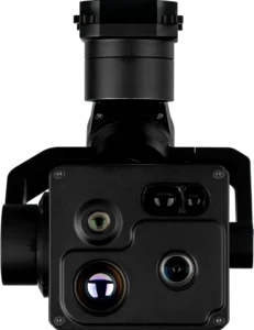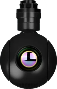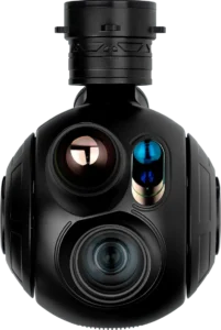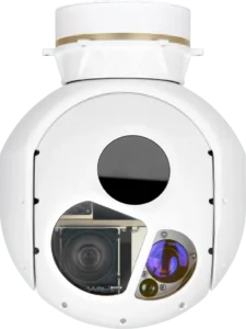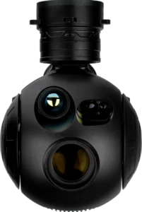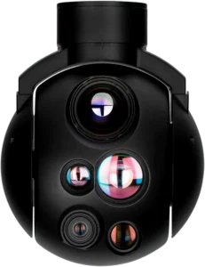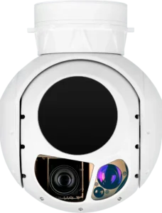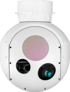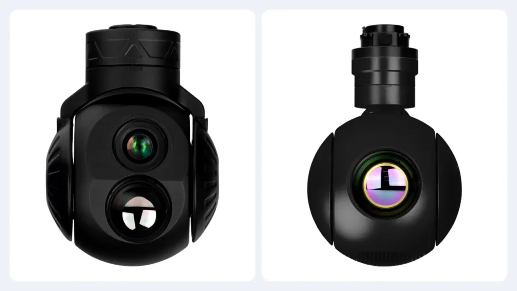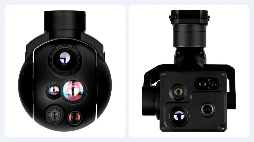
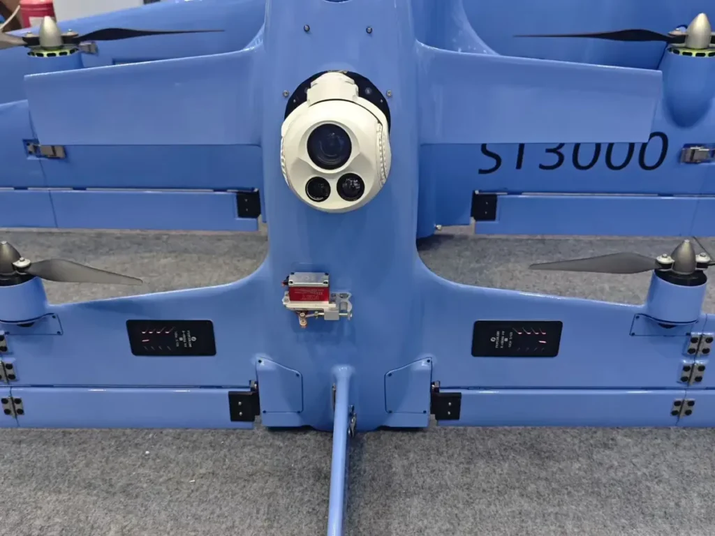
Two gimbal cameras can both list three-axis stabilisation, 30x zoom, 640 x 512 thermal and a 3 km laser rangefinder, then behave like completely different products on the same aircraft. The sheets are not necessarily wrong. They are usually describing different configurations, different test conditions or different ideas of what counts as included.
That is the problem this guide solves. If you are an OEM, integrator or technical buyer, you need a way to compare payloads that survives the brochure. The method below puts the mission first, checks the evidence behind each number and keeps the mechanical, optical, thermal and electrical claims separate until you have enough information to combine them.
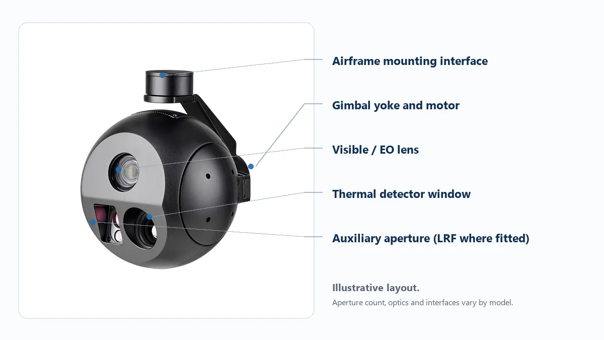
Start with a mission baseline, not a favourite model
Before you open a datasheet, write down what the aircraft has to see and what it has to do with that image. A power-line inspection sortie may need a specific insulator fitting to be distinguishable from a chosen stand-off distance. A roof survey may care more about coverage and overlap. A long-endurance VTOL may have less mass and electrical margin than a heavy multirotor.
Those are different jobs, and they do not collapse into one camera ranking. Record the smallest feature that matters, the working distance, the light conditions, the required revisit time, the airframe allowance and whether the output is live video, a recorded image or a measurement.
Write these down before comparing payloads
- Target: what must be seen or measured, and how small it is.
- Geometry: normal and worst-case distance, look angle and time on target.
- Conditions: daylight, low light, night, haze, heat contrast or vibration.
- Aircraft limits: installed mass, supply voltage, power budget and mounting space.
- Output: live video, recording, coordinates, temperature, detection or tracking.
- Evidence: what you will accept as proof before a purchase order.
This sounds obvious, but it is where many comparisons go wrong. One supplier quotes a camera head, another quotes a complete payload with mount and harness. One shows a native frame at 30x, another shows a digitally enlarged crop. If the mission baseline is vague, the specification comparison becomes a contest between incompatible numbers.
If you are still deciding what kind of payload fits the mission, start with the practical guidance in how to choose a payload around the mission and bring the shortlist back to this comparison method.
Stabilisation: axis count is architecture, not a performance score
Two axes and three axes describe mechanical arrangements. They do not, by themselves, tell you how steady the image will be, how quickly the gimbal recovers after a turn or how well it rejects vibration from a particular airframe. A well-matched two-axis head can be the sensible choice on a small aircraft. A three-axis head can be the right answer when the mission needs more controlled attitude correction. The only useful comparison is the one made under the same disturbance and the same zoom setting.
HITS builds both stabilised gimbal camera families, so this is not an argument for one architecture over the other. It is an argument for asking what was measured.
Accuracy, jitter and repeatability are different claims
Pointing accuracy is the difference between where the camera was told to look and where it actually looked. Jitter is the movement of the line of sight over time. Repeatability is whether the gimbal returns to a similar position when the same command is sent again. A single line called “stabilisation accuracy” does not tell you which of those was measured.
Ask for the test method as well as the number: fixed bench, vibration table or aircraft; camera recording or idle; zoom setting; disturbance input; frequency band; and how the result was summarised. NIST’s guidance on repeatability and reproducibility is a useful reminder that a measurement without stated conditions is not a comparison [1].
A clean hover clip does not prove that the gimbal can reacquire a target after a hard turn.
Check travel, rate and reacquisition
Yaw and pitch travel, continuous rotation, maximum commanded rate and transition behaviour all affect real missions. A fast slew figure does not prove smooth capture at high zoom. A stable close-up does not prove fast recovery after the aircraft changes heading. Request a slow tracking sequence and a repeatable commanded move across the angular range you actually need.
Do not award a stabilisation score unless the test conditions are attached to it. A number without a method is a marketing sentence, not an engineering result.
Imaging: resolution, focal length and field of view solve different problems
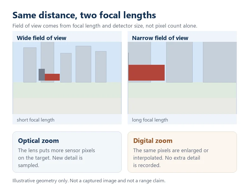
Pixel count sets an upper limit on sampled detail. It does not guarantee that a small target will be recognisable. Focal length and sensor size set the field of view. Lens quality, focus, exposure, motion and image processing decide how much contrast survives at fine detail. Long zoom enlarges the target on screen, but it also enlarges pointing error and atmospheric disturbance.
Field of view is worth keeping separate in your notes. The field-of-view reference explains the geometry, but the practical test is simpler: at the real distance and the real focal-length setting, can the operator see the feature that matters?
Do not mix optical zoom with digital enlargement
Optical zoom changes the image formed by the lens. Digital zoom enlarges or resamples the pixels you already have. A “30x optical” figure and an “up to 60x combined” figure are not the same claim. If two suppliers use different conventions, compare native frames at a matched angular field of view and an equal display size.
A larger picture is not automatically a more detailed one.
Ask for the image method, not just a beautiful sample
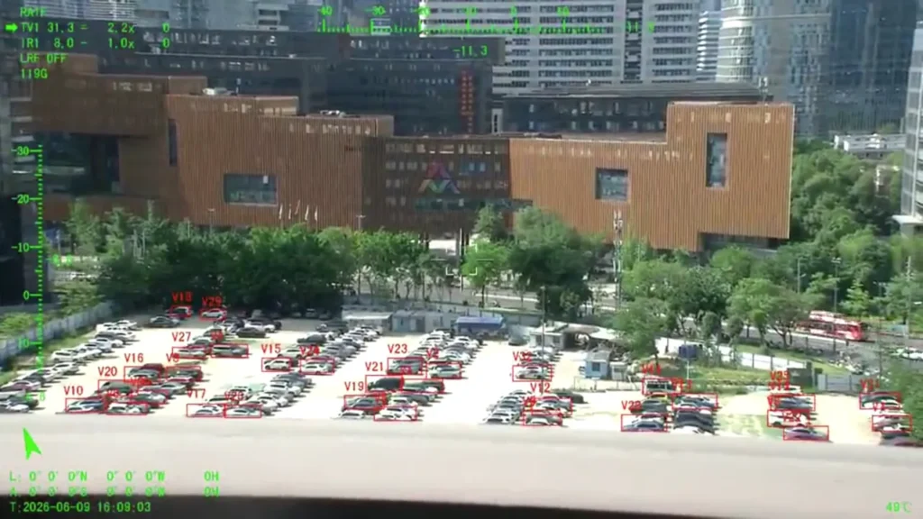
A single sample photograph can be useful, but it cannot prove a product. Ask for the original frame, the distance, the focal length, the sensor mode, the exposure settings and whether the image was cropped or enlarged. For a more disciplined comparison, use a fixed target and repeatable lighting. Standards such as ISO 12233 and EMVA 1288 are useful method references, not certificates that every payload has been tested in the same way [2].
HITS publishes separate notes on long-range imaging, including the difference between zoom ratio, focal length and usable target detail. Use those notes to set the optical requirement before you ask for a quotation.
Thermal: 640 x 512 is a starting point, not a distance guarantee
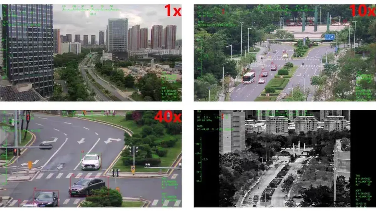
Thermal detector resolution states how many samples the detector provides. It does not state how far you can detect, recognise or identify a target. Pixel pitch, lens focal length, thermal contrast, noise-equivalent temperature difference (NETD), scene conditions and video processing all affect the usable image.
A higher-resolution detector with the wrong lens can still miss the required field of view or target detail. A lower-resolution detector with a well-matched lens and a clean processing chain can be the better system for a specific job. The NETD reference is a useful definition, but the supplier still has to tell you how the figure was measured.
Observation and radiometric measurement are not the same feature
If the task is to see relative heat contrast, a well-tuned thermal image may be enough. If the task requires defensible temperature values, you need evidence of radiometric capability, calibration, emissivity assumptions and a measurement workflow. A colourful palette is not temperature data.
For dual-channel work, ask for the visible and thermal source images separately, with each channel’s field of view and timestamp. A fusion overlay can help an operator interpret a scene, but it should not replace the separate channels during technical evaluation. HITS EO/IR pod systems are relevant when the mission genuinely benefits from co-located visible and thermal imaging, not simply because two channels sound more capable.
For a deeper comparison of detector resolution, read our 640 and 1280 thermal comparison before you use pixel count as a proxy for recognition distance.
Temperature measurement is a calibration claim, not a colour palette.
SWaP: weigh the installation, not the bare camera
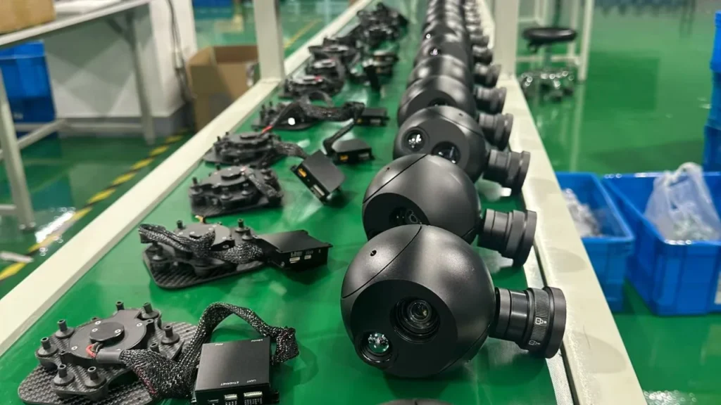
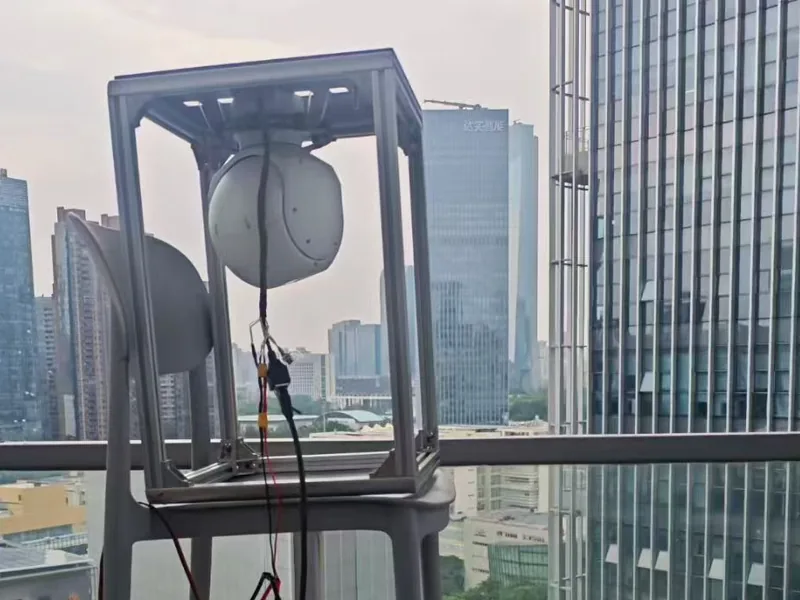
Mass figures are only comparable when they include the same parts. Does the quoted weight cover the camera head, gimbal assembly, isolation mount, connector, cable, AI board and any external controller? A supplier may quote the lightest subassembly while a competitor quotes a complete installation. That is not a comparison.
| What to record | Why it changes the answer |
|---|---|
| Installed mass | Mount, damper, harness and optional modules can move a payload into a different aircraft class. |
| Steady power | Sets the normal electrical load during cruise and imaging. |
| Peak and startup power | Can exceed the aircraft rail margin during zoom, heater operation or boot. |
| Input voltage range | Determines whether the payload can run from the aircraft’s actual bus. |
| Heat and duty cycle | Affects continuous operation, enclosure design and long-endurance missions. |
Do not accept a universal “minutes lost per kilogram” rule. Endurance depends on the airframe, aerodynamics, battery energy, flight profile and every auxiliary load. A bench power measurement and a controlled flight check are more useful than a rule of thumb.
Integration: four compatibility checks, not one “plug and play” claim
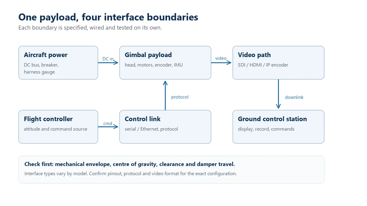
Mechanical fit, electrical connection, control protocol and video transport are separate layers. A payload can fit the bracket and still fail the protocol test. It can accept pointing commands and still refuse a recording command. It can stream video and still lack the status messages your ground station expects.
1. Mechanical compatibility
Ask for dimensioned drawings, bolt pattern, centre of gravity, cable exit, full swept envelope and isolation recommendations. A bench fit does not prove clearance when the gimbal tilts or the landing gear flexes.
2. Electrical compatibility
Check connector part numbers, pin assignments, reference ground, voltage levels and current limits. RS-232, RS-422, TTL serial and Ethernet describe electrical or transport interfaces, not a universal command language. Never assume that every model in one family uses identical wiring.
3. Control protocol
MAVLink Gimbal Protocol v2 defines roles and message structures, and PX4 documents configurable gimbal control paths [3][4]. That does not mean every payload implements every command. Ask which firmware revision was tested, which messages are supported and which functions still depend on vendor-specific commands.
4. Video and ground-station behaviour
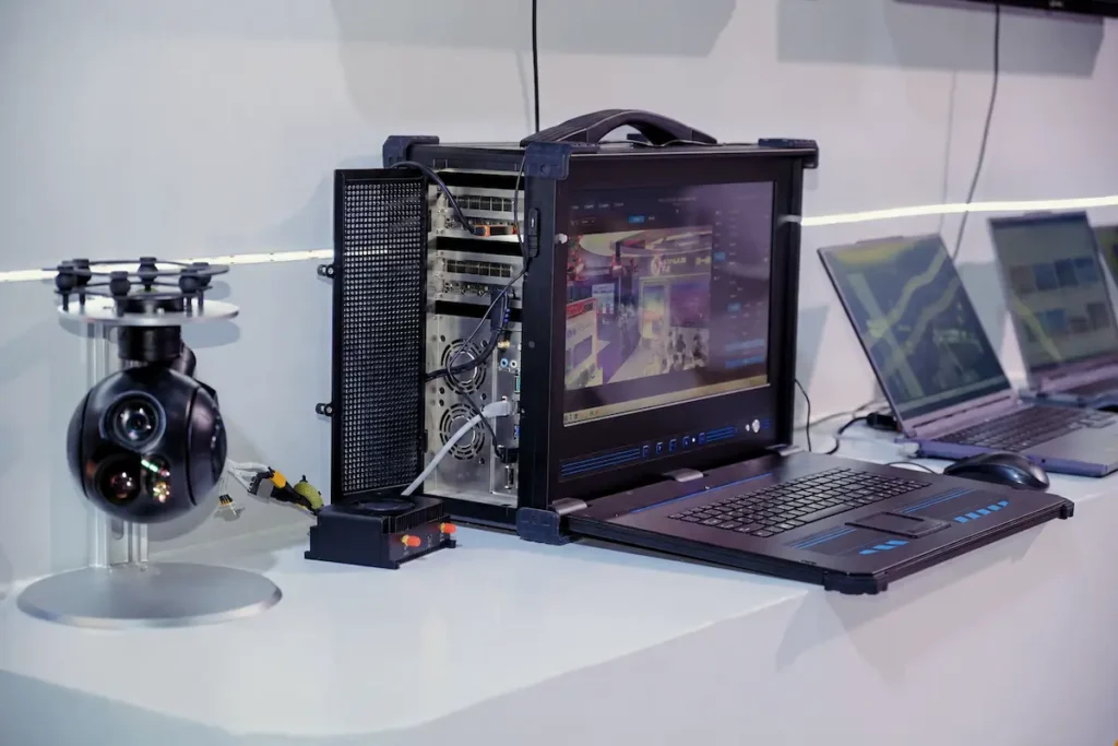
Record the actual video dimensions, frame rate, container or stream protocol, latency, recording behaviour and ground-control-station support. If RTSP and UDP appear on a datasheet, ask what each term refers to in that implementation. Seeing an image is not proof that zoom, focus, recording, palette and tracking all work.
The UAV payload integration guide covers the hardware and MAVLink side in more detail. Use it to prepare the interface questions before a sample arrives.
A working video feed is not proof of full control compatibility.
Build a scorecard after the mandatory gates
Start with pass or fail requirements, not points. If a payload cannot fit the aircraft, run from the available voltage or deliver the essential imaging channel, no optical score can rescue the project. Only candidates that pass those gates belong in the weighted comparison.
| Criterion | Illustrative weight | Evidence to request |
|---|---|---|
| Target-level imaging detail | 25% | Native frame at mission distance, recorded FOV and exposure |
| Pointing and stabilisation | 20% | Defined test method, units and representative logs |
| Aircraft SWaP fit | 20% | Complete installed mass and measured power profile |
| Control and video integration | 20% | ICD, pinout, firmware revision and command test |
| Environmental and support readiness | 15% | Model-specific conditions, test records and change plan |
The weights are illustrative. Change them to match the mission. What should not change is the evidence rule: a documented supplier claim, a repeatable in-house test and an independently checked result are three different levels of confidence. If a number is missing, mark it “not demonstrated”. Do not treat it as zero, and do not award it the best-case value.
A six-step verification plan that fits a real project
- Document review: exact model, firmware, optics, installed mass, power and supported interfaces.
- Bench fit: mechanical clearance, safe power-up, connector check and thermal behaviour.
- Control test: discovery, mode changes, zoom, focus, recording, status and recovery.
- Video test: stream format, latency, recording and ground-station display on the intended chain.
- Image test: fixed target at the real distance, native frames, matched FOV and recorded settings.
- Disturbance test: vibration table or representative aircraft flight, followed by a signed exception log.
Write the pass rule before you see the result. If the criterion is “the operator can hold a person-sized target in the centre third of the frame during a 300 m orbit”, write that down. Do not wait for the footage and then decide whether it looks good enough.
If a payload fails a mandatory gate, change the payload or the requirement. Do not quietly move the gate.
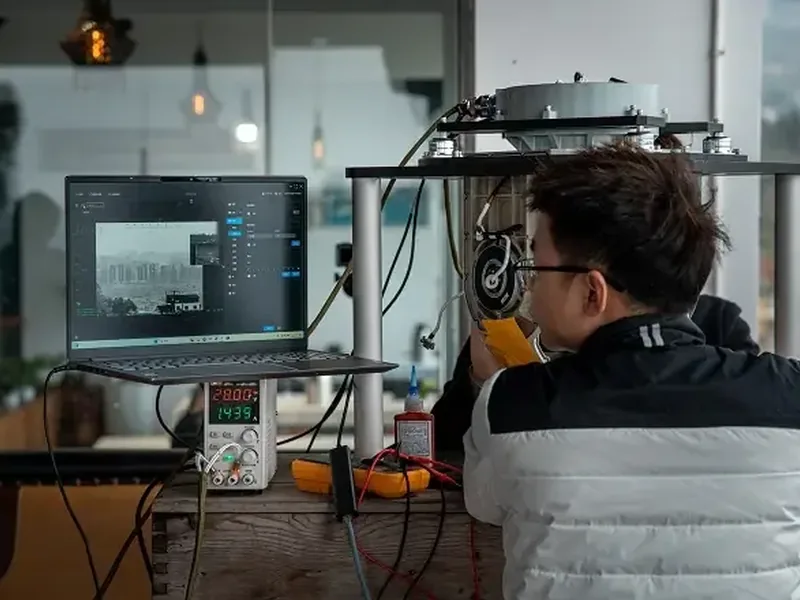
Questions to send before a technical RFQ
- Which exact model, sensor configuration and firmware revision does each quoted figure describe?
- What test conditions, units and sample size sit behind the stabilisation claim?
- Can you provide native EO and IR frames at our mission distance and focal-length setting?
- What is the installed mass with mount, damper, harness and every required module?
- What are the steady, peak and startup power figures, and over which voltage range?
- Can we review the current mechanical drawing, connector pinout and interface control document?
- Which video formats and control commands have been demonstrated with our autopilot and ground station?
- Which functions are still vendor-specific rather than standard MAVLink or PX4 commands?
- What happens after a temporary link loss, a power cycle or an unsupported command?
- Which limitations, support arrangements and firmware change process apply to an OEM programme?
If you send those questions with the aircraft type, mission distance, allowable installed mass, supply voltage and video chain, a supplier can answer something useful. Without them, every reply turns into another brochure.
Frequently asked questions
What is the most important UAV gimbal camera specification?
There is no single number. The most important value is the one tied to the mission acceptance test, such as resolved target detail at a stated distance or a successful control and video test on the selected airframe. Mandatory aircraft limits come first.
Is a three-axis gimbal always better than a two-axis model?
No. It adds mechanical options, not a guaranteed image result. Compare line-of-sight behaviour, mass, power and integration on the actual aircraft and in the actual disturbance conditions.
Does a higher-resolution camera always produce better inspection images?
No. Lens quality, focal length, focus, exposure, motion, processing and compression all affect usable detail. Native frames from matched conditions are more useful than a pixel count on its own.
Is MAVLink support enough for plug-and-play integration?
No. Supported messages, manager and device roles, firmware revision, wiring and video transport all need checking. A successful pointing command does not confirm zoom, recording, thermal palette or AI functions.
How should we compare two incomplete datasheets?
Mark missing values as unverified, ask both suppliers for the same evidence package and do not award points for claims you cannot test. A short sample evaluation is often cheaper than guessing.
What a good comparison leaves you with
A useful comparison ends with a shortlist you can defend, not a folder of brochures. You should know which payloads pass the aircraft limits, which ones have evidence at the real mission distance and which integration questions remain open. You should also know what you have not verified.
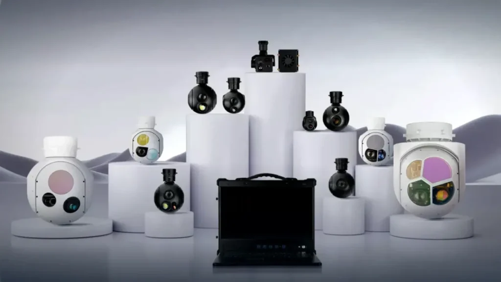
HITS publishes its industrial UAV camera range with separate EO, thermal, EO/IR and laser-designator configurations. The right starting point is not the largest number on the page. It is the configuration that meets the mission, fits the aircraft and comes with evidence you can check.
If you have the aircraft, distance, mass limit and interface details, send the platform details to our payload team. We can narrow the range and tell you which documents and tests are needed before a sample evaluation.
Put your payload shortlist on a real test plan
Send the aircraft type, working distance, imaging requirement, installed mass limit and control interface. HITS will help you compare the relevant configurations without turning the decision into a brochure contest.
Sources and method notes
- NIST Technical Note 1297, guidance on measurement terminology, repeatability and reproducibility.
- EMVA Standard 1288, a framework for characterising image sensors and cameras. It is a method reference, not a HITS certification.
- MAVLink Gimbal Protocol v2, roles and message definitions for gimbal control.
- PX4 gimbal configuration, control routing and configuration guidance. Support must still be verified per payload and firmware revision.
- Field of view, background on angular coverage and optical geometry.
- NETD, background on thermal sensitivity and measurement conditions.
Standards and protocol documents describe methods and possible architectures. They do not prove that a particular payload, firmware revision or aircraft configuration has passed the same test.