
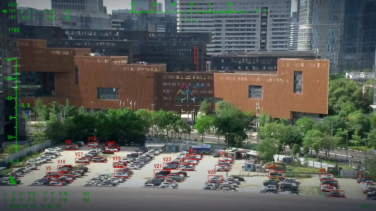
Electro-Optical Resources: Sensors, Systems and Payloads
Reference pages for sensor, system and payload selection
These pages are written for the person who has to specify a sensing channel: what the bands actually do, how a sensor is matched to a lens, how two channels are boresighted, and where the limits sit.
- Spectral bands
- Sensor formats
- Lens matching
- Boresight
Reference pages
Sensor first, then the pair, then the system.
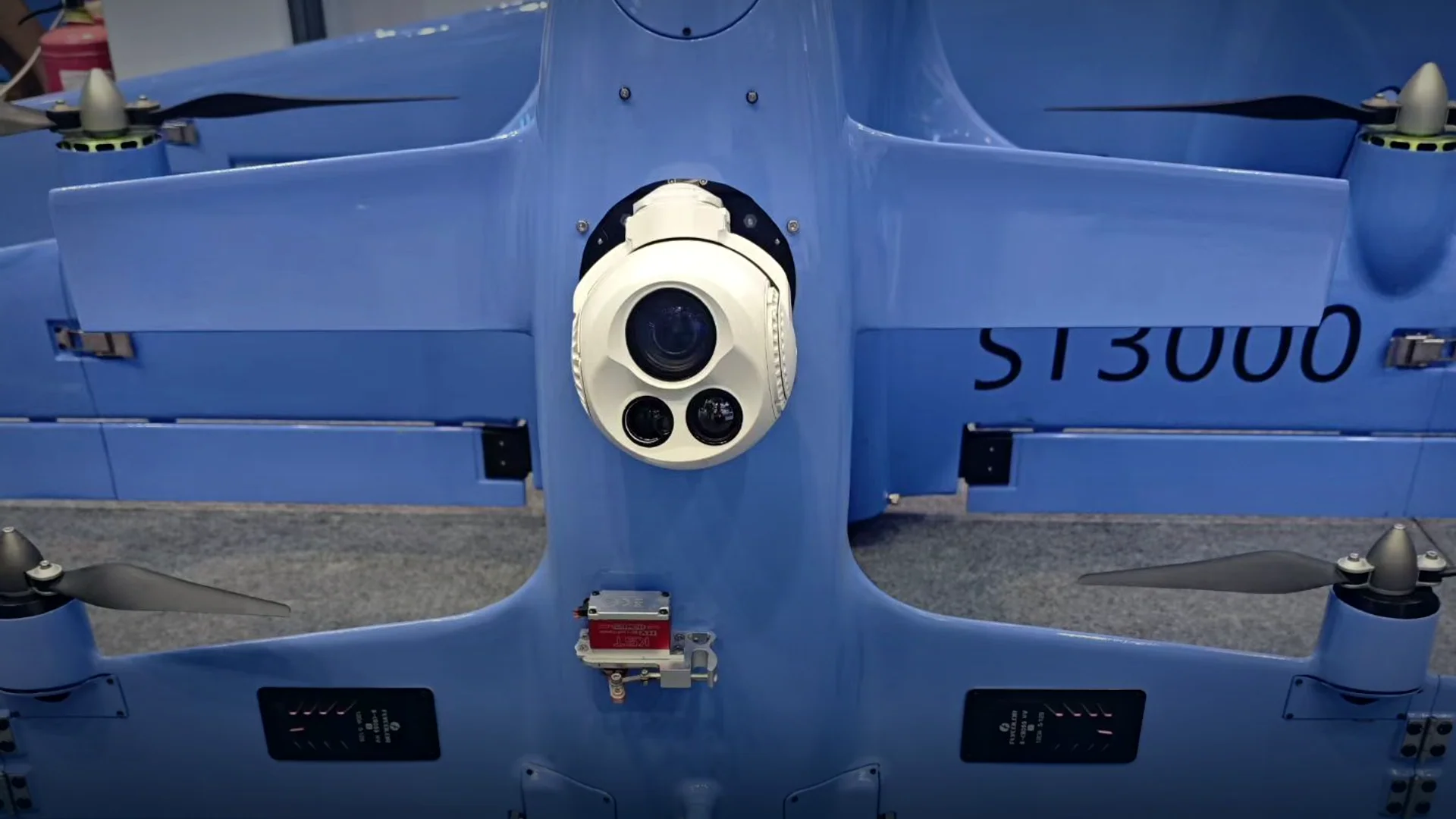
- System levelElectro-Optical Systems
How sensors, optics, stabilisation and data interfaces come together into a usable airborne payload.
- Sensor levelEO Sensors
Formats, pixel pitch, shutter behaviour and lens matching for the visible channel.
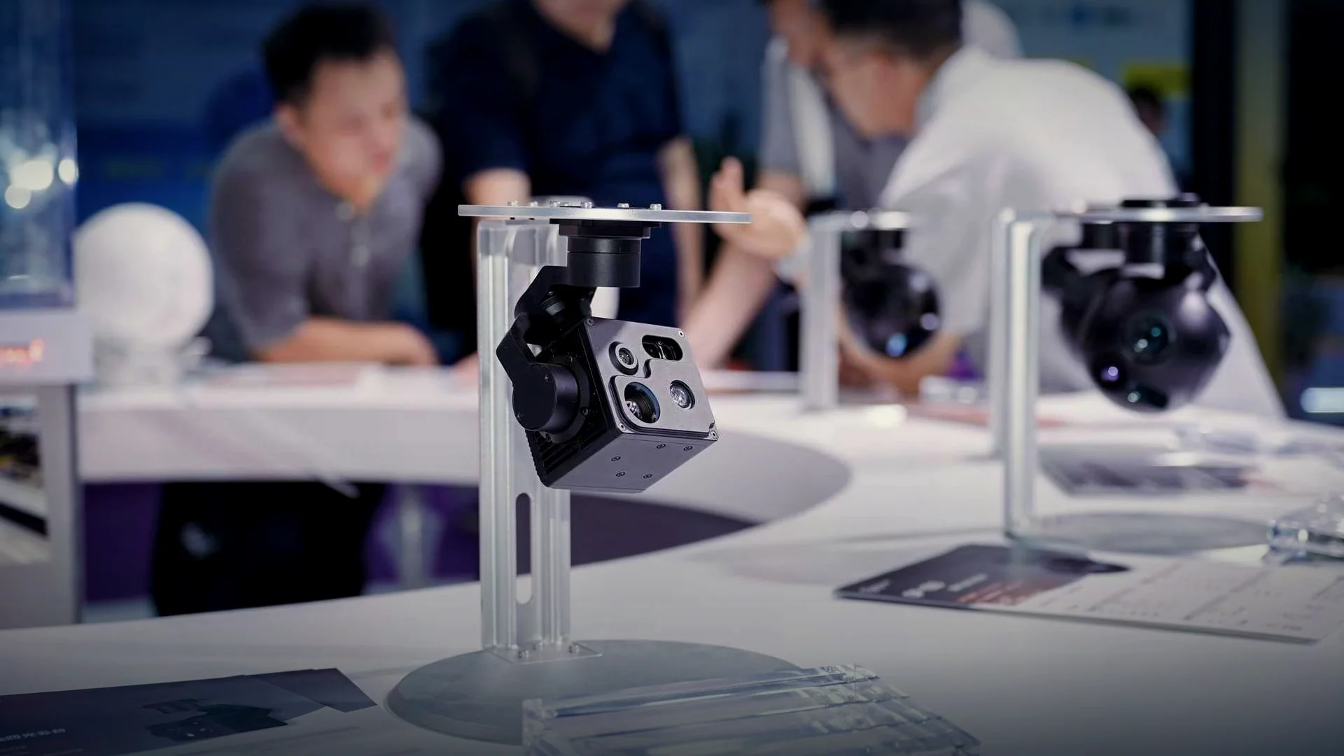
- Pairing levelEO/IR Sensors
Detector types, band pairing and boresight tolerances for dual-channel imaging.
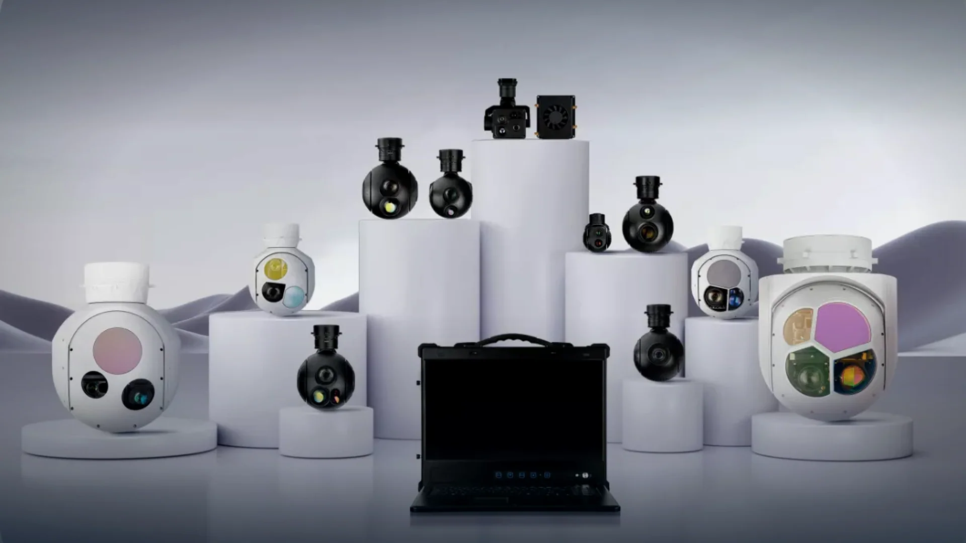
The three pages below cover the same subject at three levels: the sensor itself, the pair of sensors that makes a dual-channel payload, and the complete electro-optical system that carries them. Read in that order they answer the questions that come up before a payload is chosen, rather than after, and together they form the eo/ir resources an integrator needs to compare payloads on equal terms.
Nothing here is specific to a single model. Where a number is given it is a property of the band, the detector technology or the geometry of a boresight, so it applies whether you are specifying a 240 g inspection head or a 22 kg targeting turret.
The three levels
- The sensor
Format, pixel pitch, shutter type and sensitivity decide how much information a channel can carry before anything is done with it.
- The pair
Boresight, band pairing and detector choice decide whether visible and thermal images can be used as one picture.
- The system
Optics, stabilisation, processing and the data interface decide whether the sensor can be used from a moving aircraft at all.
Spectral bands at a glance
The bands that matter for airborne imaging payloads, and what each one is actually good at.
| Band | Wavelength | Detector | Strength | Limit |
|---|---|---|---|---|
| Visible | 0.4 – 0.7 µm | CMOS | Colour, detail, human interpretation | Needs light; degrades in haze |
| Near infrared | 0.7 – 1.1 µm | CMOS or InGaAs | Works with 850 / 940 nm illumination | Illumination can be detected |
| Short-wave infrared | 1 – 3 µm | InGaAs | Sees through some haze and smoke | Expensive; low resolution per cost |
| Mid-wave infrared | 3 – 5 µm | Cooled MCT or InSb | Hot targets, long range in dry air | Cryocooler cost, weight and power |
| Long-wave infrared | 8 – 14 µm | Uncooled microbolometer | Passive thermal imaging at ambient temperature | Lower resolution per detector size |
Related pages
Reference material sits alongside the product and technology pages.
- TechnologyNight vision, long range imaging and AI tracking.Read more →
- Thermal camerasThermal configurations from 640 x 512 to 1280 x 1024.Read more →
- EO/IR camerasTwelve dual-sensor payloads in the range.Read more →
How to use these pages
Read the band before the sensor
Most specification mistakes are band mistakes: expecting a visible camera to work at night, or a long-wave detector to resolve a licence plate. Choose the band from the mission first, then the sensor from the band.
Then check the geometry
Field of view, instantaneous field of view and boresight tolerance are geometry, and geometry decides how many pixels land on the object and whether two channels agree about where it is.
Designed and manufactured by HITS
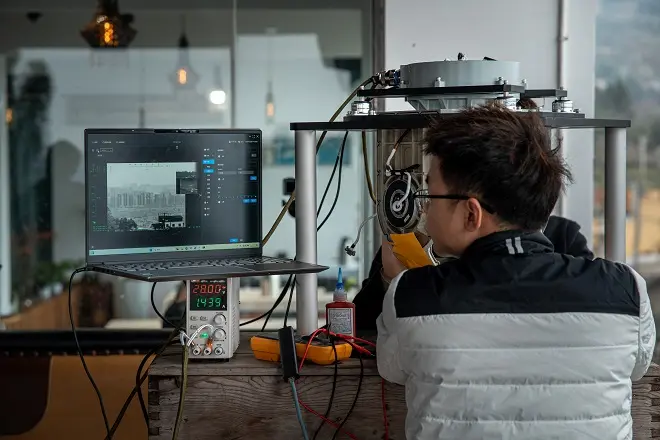
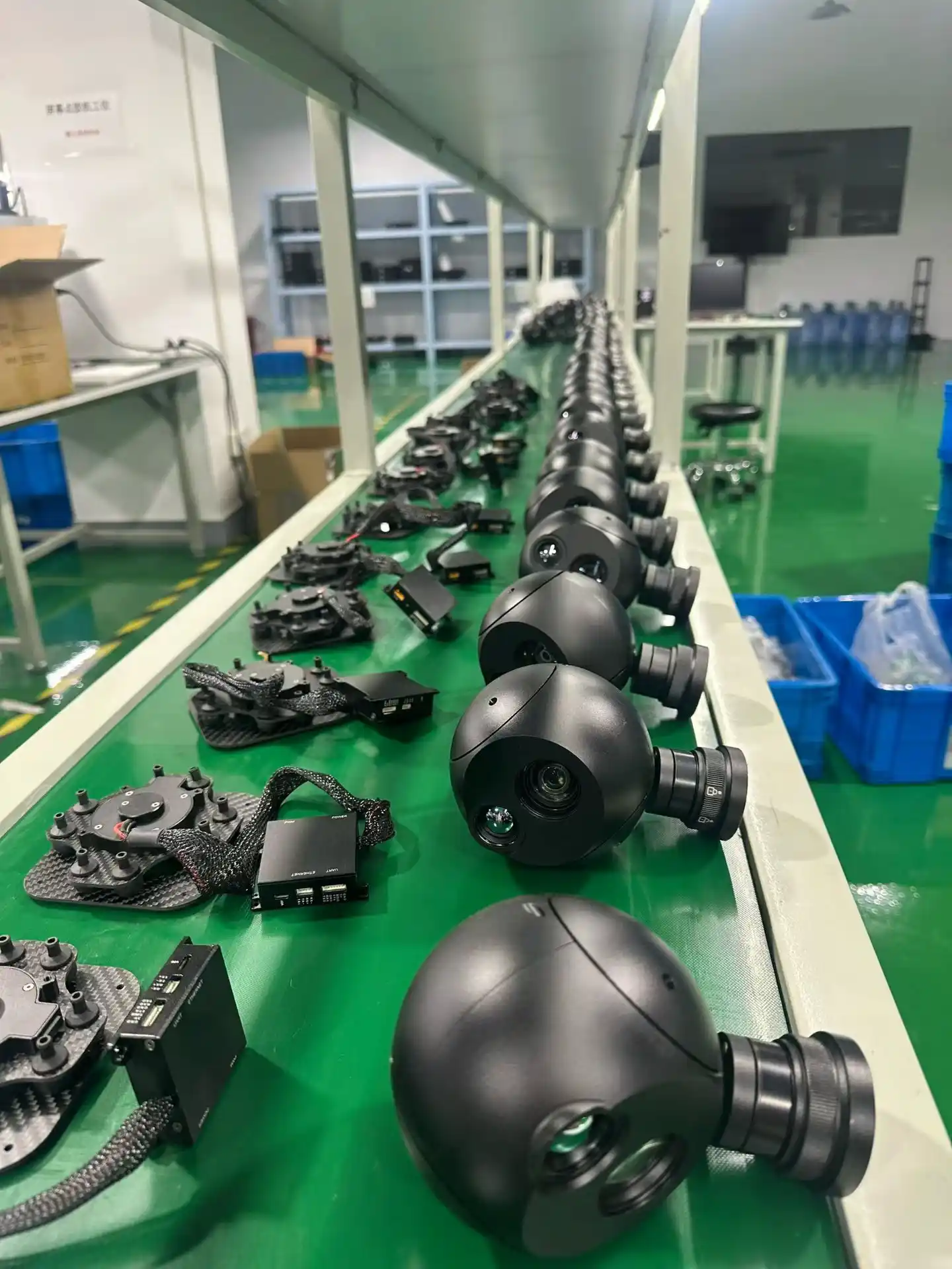
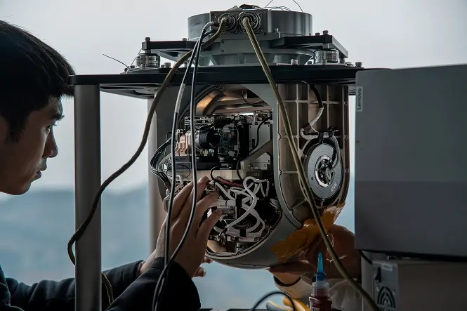
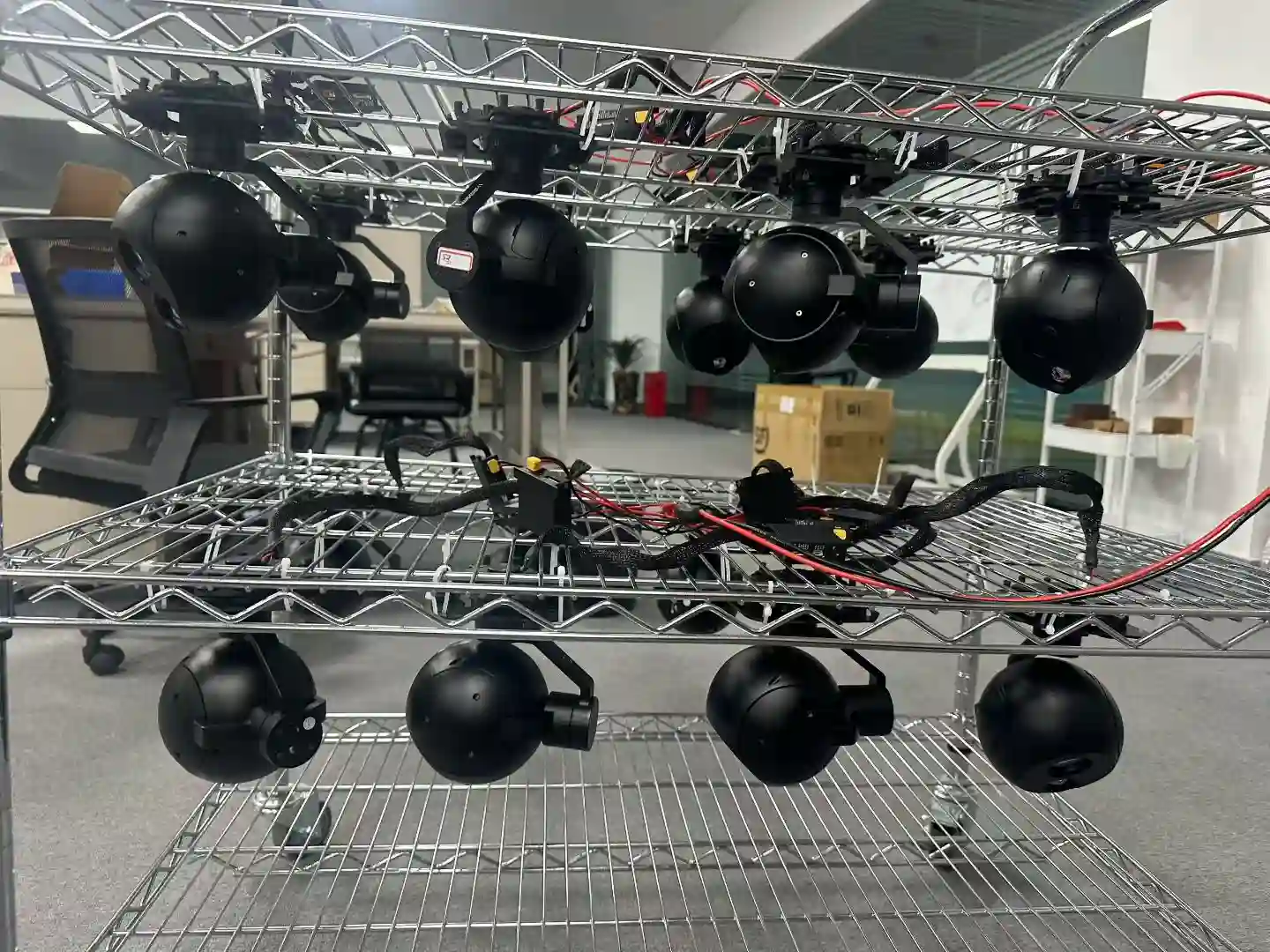
Optics, servo hardware, stabilisation firmware and the AI tracking module are developed in house, and every unit is assembled, calibrated and environmentally tested on our own line before it ships.
Related reading
Request information or a quotation
If a specification is ambiguous, send it over and we will tell you what it means in practice. Contact us with your requirements.