
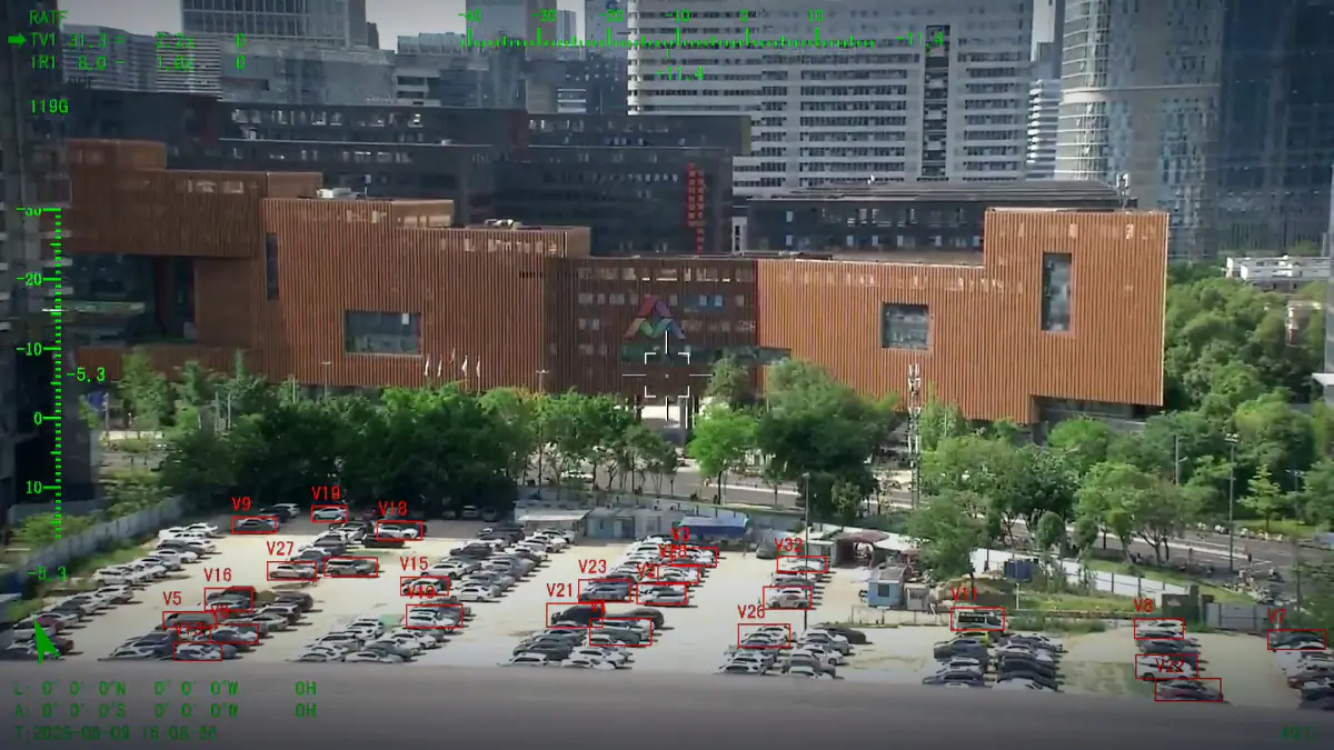
Electro Optical Systems: From Sensor to Stabilised Payload
How a sensor becomes a usable airborne payload
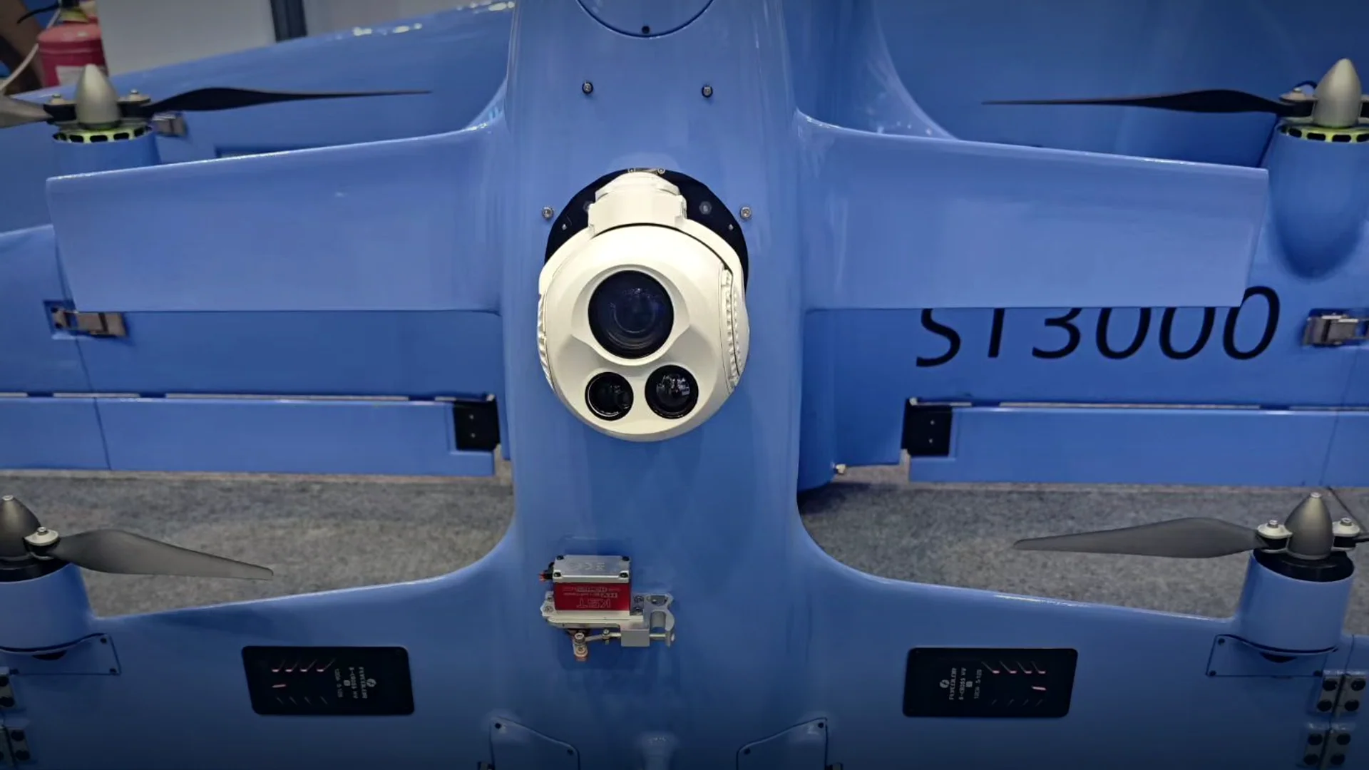
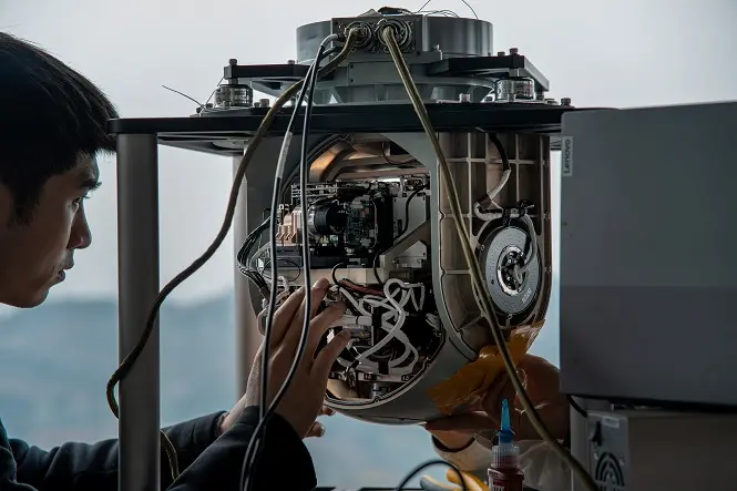
An electro-optical system is more than a sensor and a lens. It is an optical assembly, a stabilised mount, an imaging head with one or more channels, a processing module and a data interface, and the performance of the whole is set by the weakest of those parts.
- Optical assembly
- Stabilised mount
- Single or dual channel
- Processing module
Electro-optical systems convert photons into a stabilised, georeferenced image that somebody can act on. In an airborne payload that chain runs from the front lens, through the sensor, into processing that stabilises, compresses and where required tracks, and out through a video and control interface. Written as one word or two, electro optical systems and electrical optical systems both describe the same field: the engineering of imaging systems that use light rather than radar or acoustics. Misspellings such as electic optical systems mean the same thing.
The practical reason to think in systems rather than components is that the familiar failures are interface failures. An excellent eo system with an incompatible control protocol will not fly; a well-specified sensor behind a mediocre mount will not hold a target at zoom; and two channels that are not boresighted will not agree about where the object is, however good each one is on its own.
The five stages of a payload
- Optical assembly
Front lens, zoom group, focusing group and coatings. Focal range sets field of view; aperture sets light gathering; coating set is chosen for the band the sensor uses.
- Sensor and channel count
A single visible channel, a single thermal channel, or a boresighted pair with an optional laser. More channels cost weight, power and video bandwidth, which is why most eo/ir systems carry two and the smallest eo ir systems carry one.
- Stabilised mount
Two or three direct-drive axes with high-resolution encoding. Stabilisation accuracy is a system property: it depends on the optics as much as on the servos.
- Processing module
Image stabilisation, compression, recording, detection and tracking. Running it on the payload removes the data link from the control loop.
- Data interface
Ethernet video with RS-422, RS-232, TTL, SBUS or MAVLink control. This is the stage that decides whether the payload can be integrated at all.
- Environmental envelope
11 – 28 VDC, -20 C to +60 C operation, IP54 sealing and vibration tolerance sized to the platform rather than to a bench.
Where performance is lost
A system view of the four places airborne imagery usually degrades.
| Stage | What goes wrong | What fixes it |
|---|---|---|
| Optics | Field of view too wide for the detection range, or too narrow to find anything | Choose focal range from the mission, not from the zoom ratio |
| Sensor | Pixels on target too few at the required range | Match detector pitch and format to the focal length |
| Mount | Jitter at high zoom, gear backlash, slow recovery after a gust | Direct-drive axes, high-resolution encoding, high loop rate |
| Channels | Visible and thermal disagree about the target position | Factory boresight on one cage, checked across temperature |
| Interface | Payload cannot join the airframe or the ground station | Published protocol and support for Ethernet, RS-422, RS-232, TTL, SBUS, MAVLink |
| Environment | Condensation, dust ingress, temperature drift | IP54 sealing and full-range temperature testing before shipping |
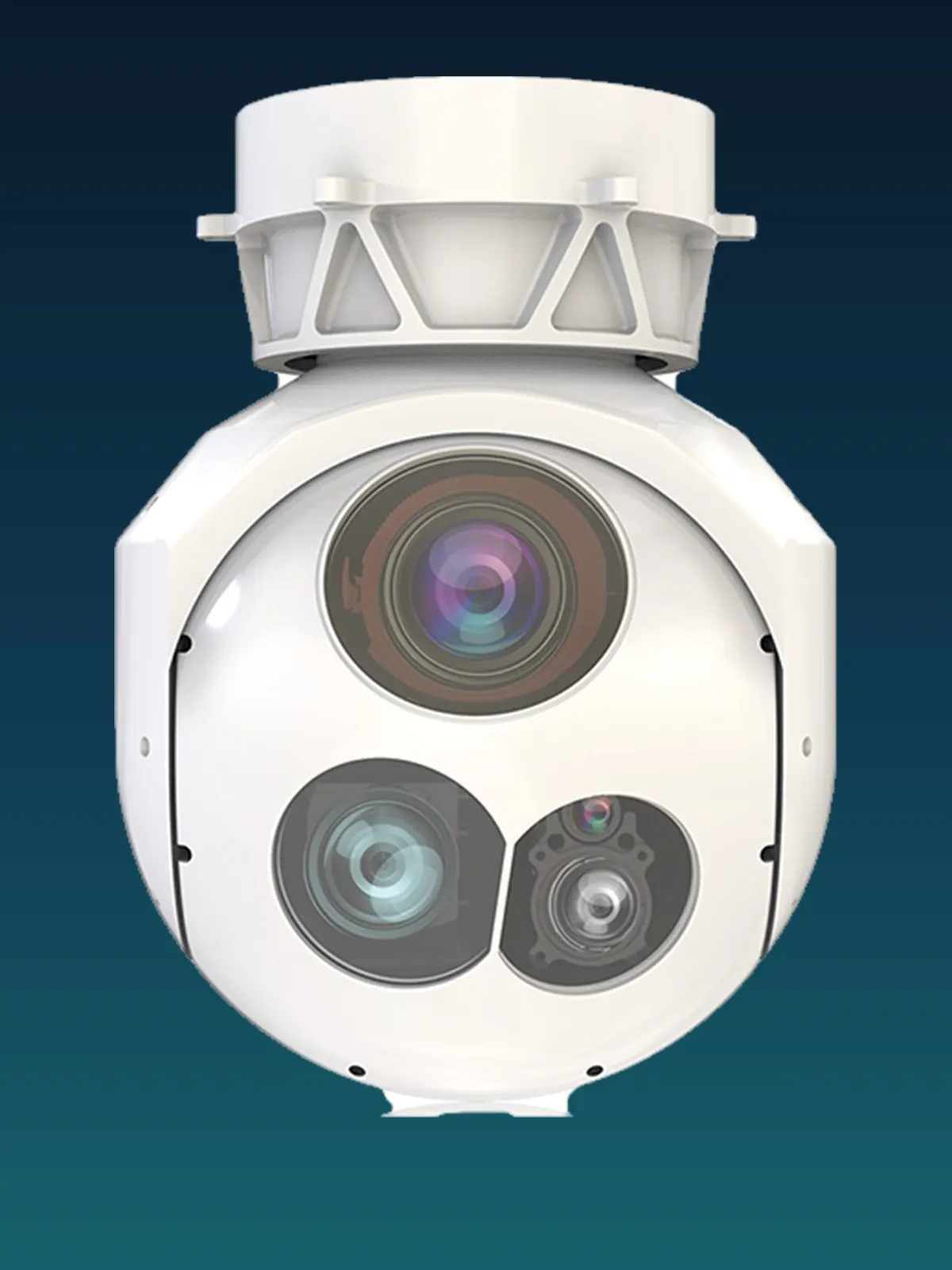
Three systems built to this pattern
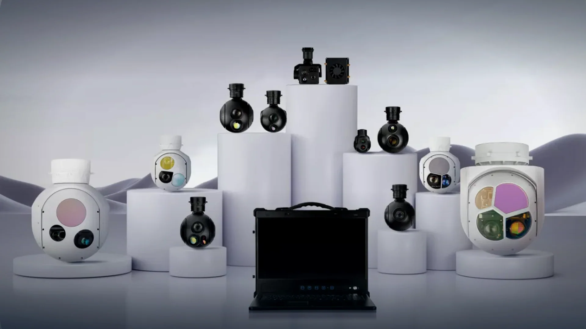
A 400 g three-axis head, a 1.4 kg long-lens head and a 5 kg pod class turret.
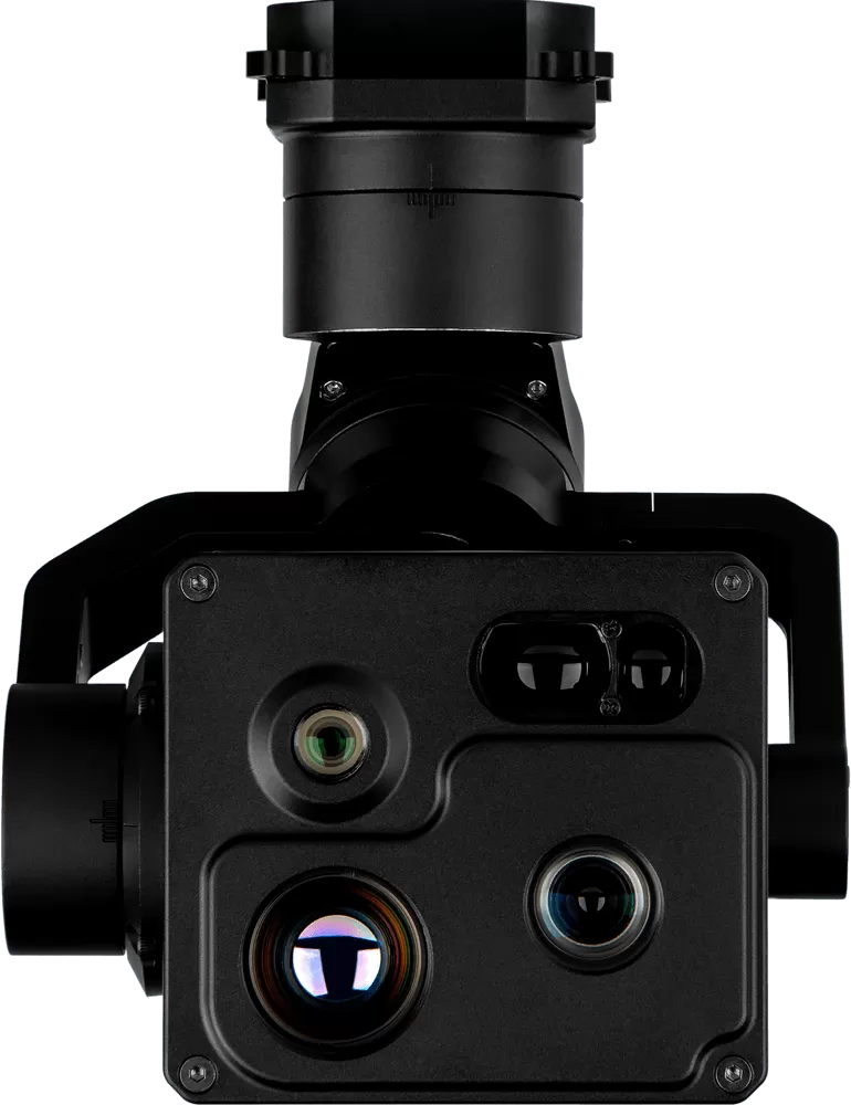
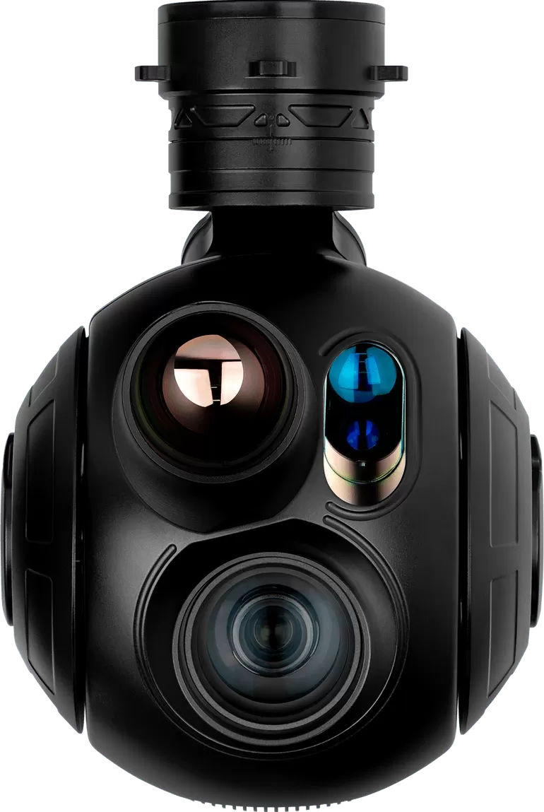
HQ · 3-axis · EO + IR + LRF
HQ-95Q
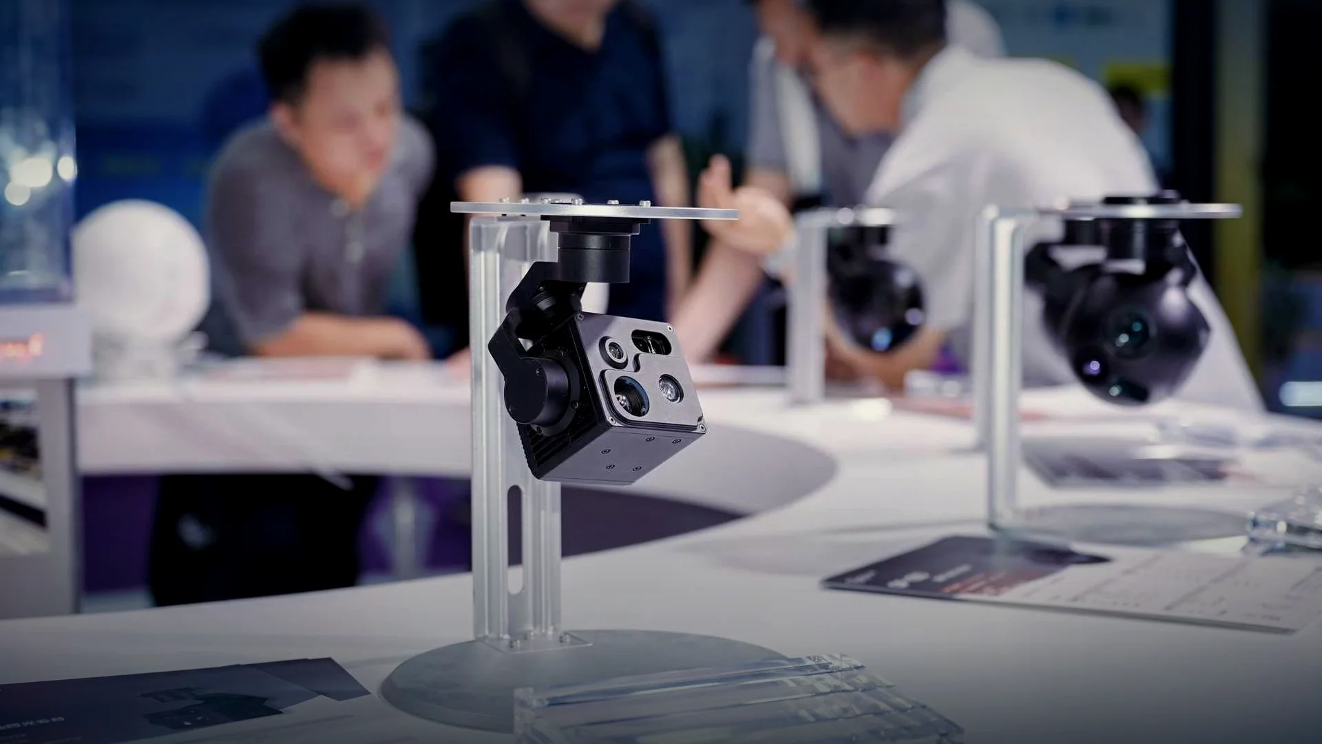
Four optical channels and a quick-release mount on the lightest three-axis head we build.
- Visible
- Dual 8000 × 6000, 9.5 mm + continuous zoom 15.3 – 49.7 mm
- Thermal
- 640 × 512, 19 mm fixed
- Laser
- 5 m – 1.5 km (± 1 m)
- Weight
- ≤400 g
HQ · 3-axis · EO + IR + LRF
HQ-135T
The flagship of the compact range: 40x zoom, thermal imaging and 3 km ranging on one stabilised cage.
- Visible
- 1920 × 1080, 40x zoom 4.25 – 170 mm
- Thermal
- 640 × 512, 35 mm fixed
- Laser
- 15 m – 3 km (± 1 m)
- Weight
- ≤1.4 kg
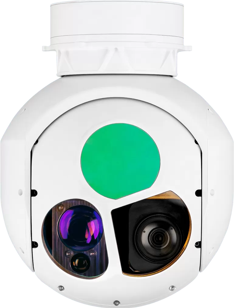
XQ · 2-axis · EO + IR + LRF
XQ-200T
A continuous-zoom thermal channel from 40 mm to 220 mm plus 9.5 km ranging on a 5 kg pod.
- Visible
- 1920 × 1080, 30x zoom 4.3 – 129 mm
- Thermal
- 640 × 512, continuous zoom 40 – 220 mm
- Laser
- 50 m – 9.5 km (± 1 m)
- Weight
- ≤5 kg
Compare the range
| Model | Series | Axes | Configuration | Visible camera | Thermal imager | Laser rangefinder | Weight |
|---|---|---|---|---|---|---|---|
| HQ-95Q | HQ series | 3-axis | EO + IR + LRF | Dual 8000 × 6000, 9.5 mm + continuous zoom 15.3 – 49.7 mm | 640 × 512, 19 mm fixed | 5 m – 1.5 km (± 1 m) | ≤400 g |
| HQ-135T | HQ series | 3-axis | EO + IR + LRF | 1920 × 1080, 40x zoom 4.25 – 170 mm | 640 × 512, 35 mm fixed | 15 m – 3 km (± 1 m) | ≤1.4 kg |
| XQ-200T | XQ series | 2-axis | EO + IR + LRF | 1920 × 1080, 30x zoom 4.3 – 129 mm | 640 × 512, continuous zoom 40 – 220 mm | 50 m – 9.5 km (± 1 m) | ≤5 kg |
Specifying an electro-optical system
Start from the decision the imagery supports
Detection, recognition and identification are three different requirements. Write down which one the mission needs, and at what range, before any sensor is discussed. The answer usually removes half of the catalogue immediately.
Then work through the chain
- Band: visible, thermal or both. If the mission runs at night, thermal is the primary channel.
- Field of view at both ends of the zoom, not just the magnification figure.
- Pixels on target at the required range, which needs detector format, pitch and focal length together.
- Stabilisation accuracy appropriate to the longest focal length the operator will actually use.
- Interface and power, checked against the airframe rather than assumed.
Common mistakes
Comparing zoom ratios between payloads with different focal ranges; specifying the sensor without the lens; treating a rangefinder figure as an imaging range; and leaving integration to the end of the project, when the control protocol is the one thing that cannot be changed later.
Related pages
The system view sits above the component pages.
- EO sensorsFormats, pixel pitch and lens matching.Read more →
- EO/IR sensorsDetectors, bands and boresight tolerances.Read more →
- EO camerasVisible channels from 2K to 48 MP.Read more →
- Gimbal camerasThe heads these systems are built into.Read more →
Engineering detail
Why zoom ratio is a misleading number
A 30x zoom on a 4.3 mm lens reaches 129 mm; a 30x zoom on a 10 mm lens reaches 300 mm. The ratio says nothing about either end of the range, and two payloads quoting 30x can differ by more than a factor of two in reach. Compare focal lengths and fields of view instead.
Why boresight is a systems problem
Aligning two channels on a bench is straightforward. Keeping them aligned through a temperature range, vibration and a zoom movement is a structural problem: the two optical paths have to share a cage with matched expansion, and the alignment has to be verified after the assembly has been temperature cycled.
Why the payload should own the processing
Every function moved to the ground station adds a link to the control loop. Detection, tracking, stabilisation and recording on the payload mean a degraded or dropped link costs the operator a picture, not a mission.
Designed and manufactured by HITS
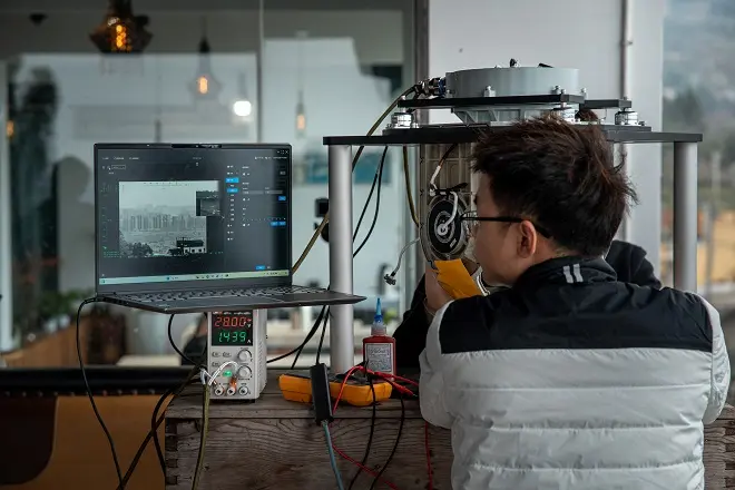
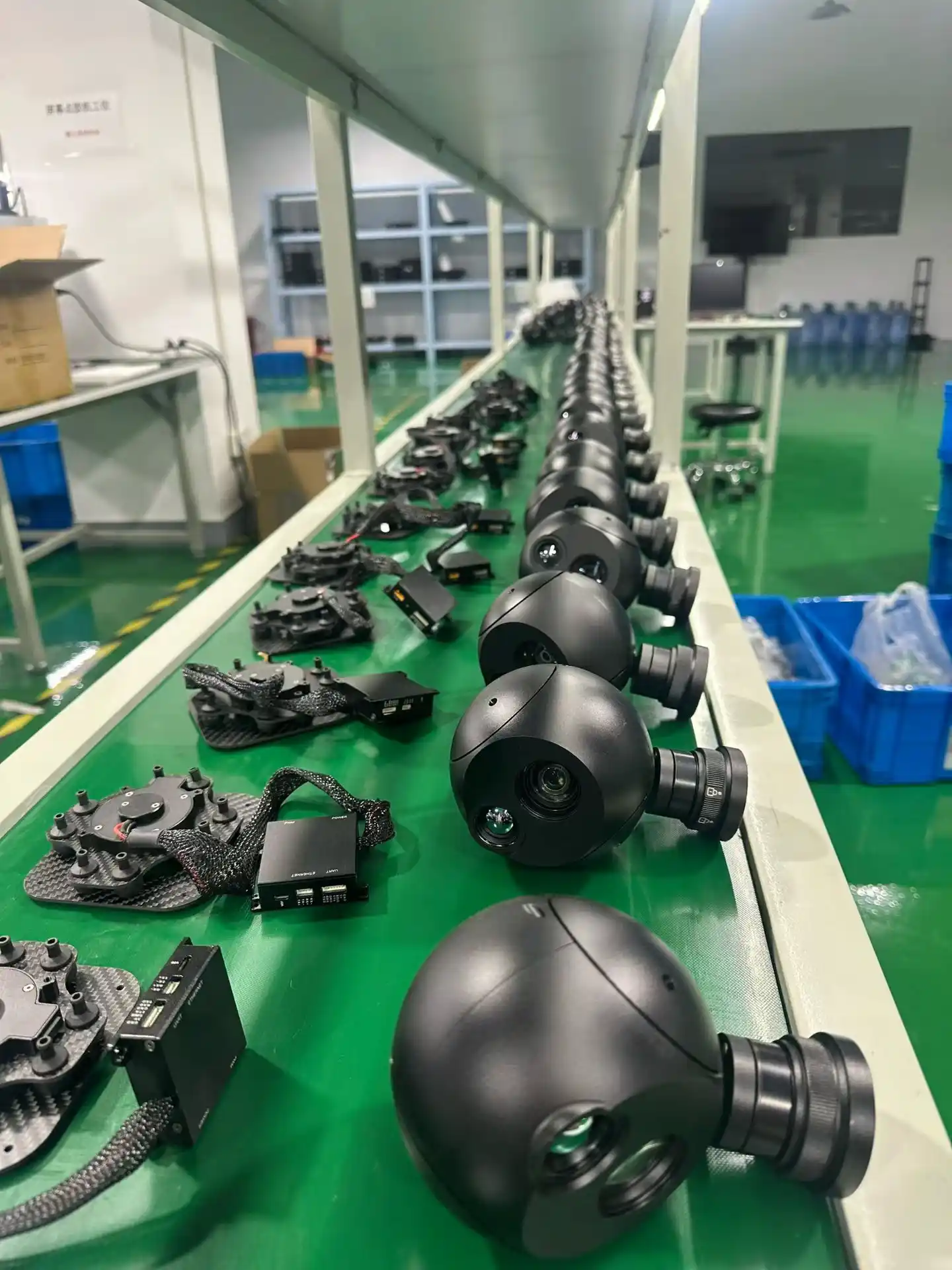
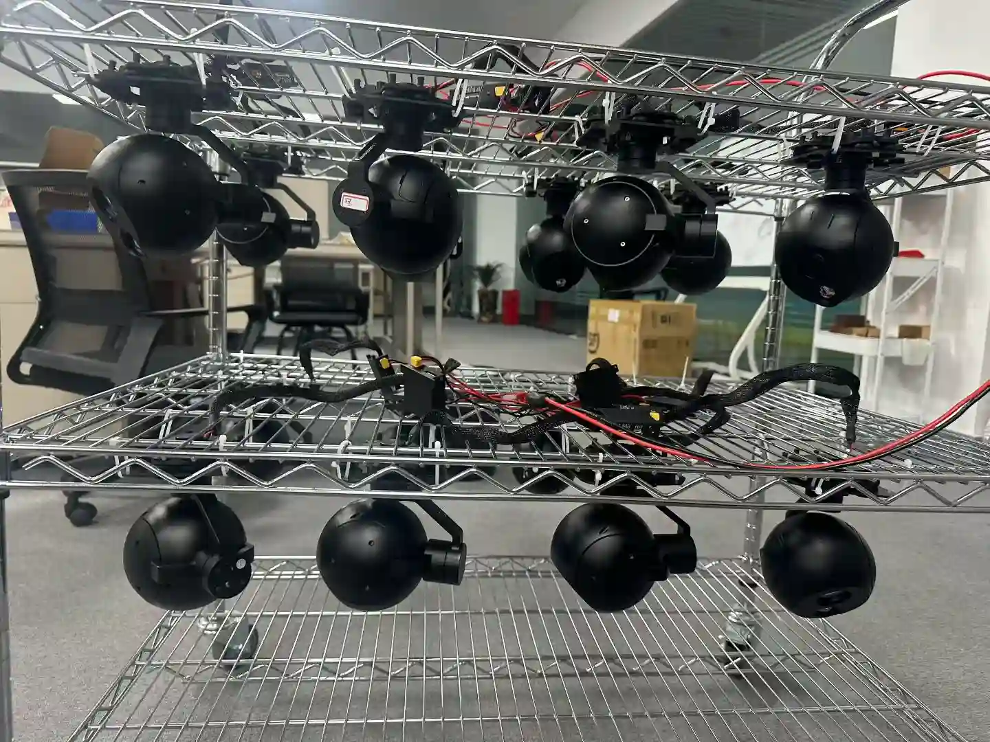
Optics, servo hardware, stabilisation firmware and the AI tracking module are developed in house, and every unit is assembled, calibrated and environmentally tested on our own line before it ships.
Request information or a quotation
Send us the requirement and we will map it onto a system rather than a component. Contact us with your requirements.