A payload factory, not a trading desk.
Optics selection and alignment, gimbal mechanics, servo hardware, stabilisation firmware and the AI tracking module are all developed in house. Every unit is assembled, calibrated and environmentally tested on our own line before it is packed, which is why the figures on the model pages can be reproduced on the unit you receive.
Factory-direct dialogue from an initial evaluation to the intended production configuration.
What comes off this line.
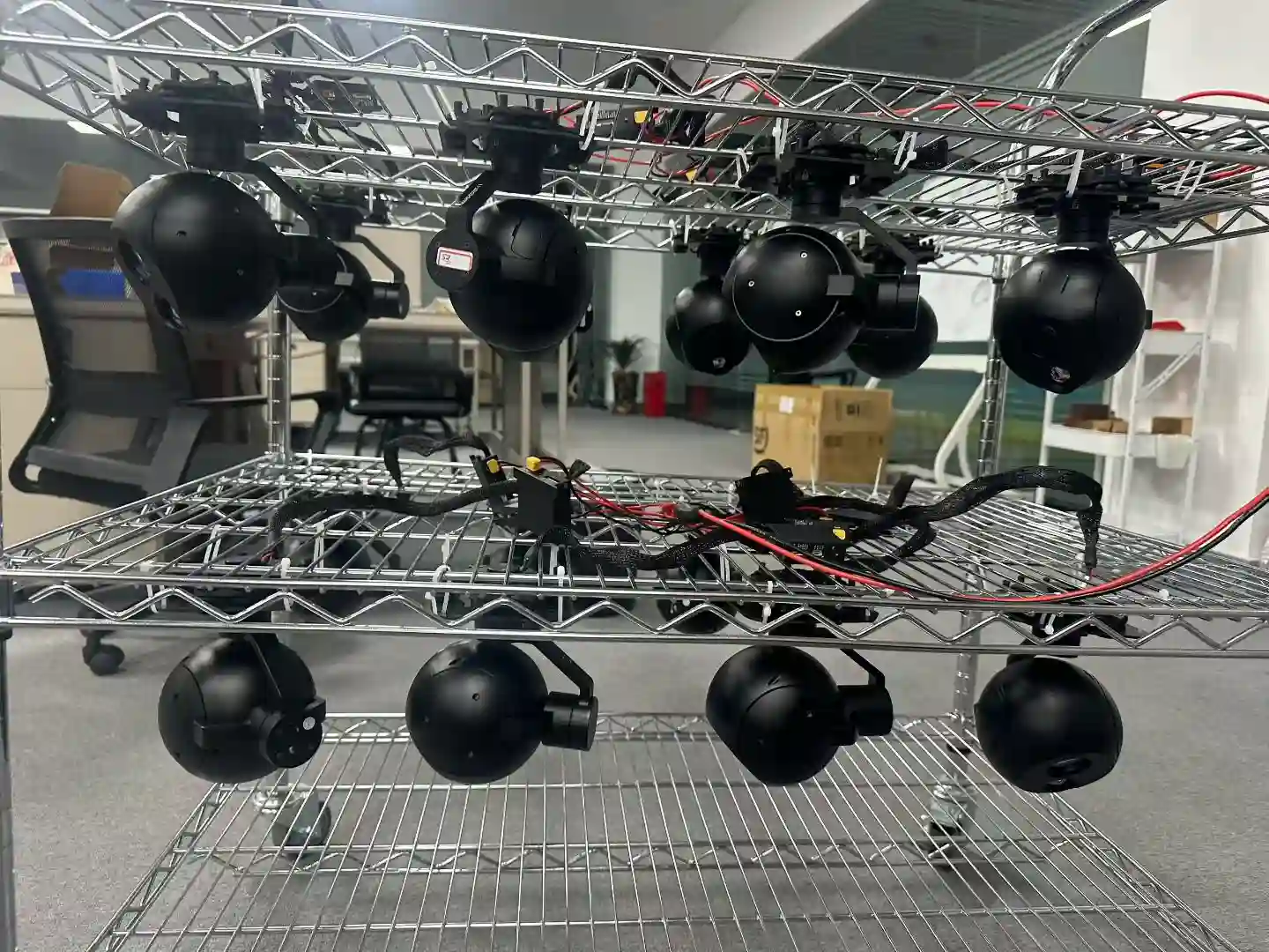
Two-axis and three-axis gimbal camera payloads from 240 g to 22 kg, in EO, thermal, EO/IR and laser rangefinder configurations. See all 27 models →
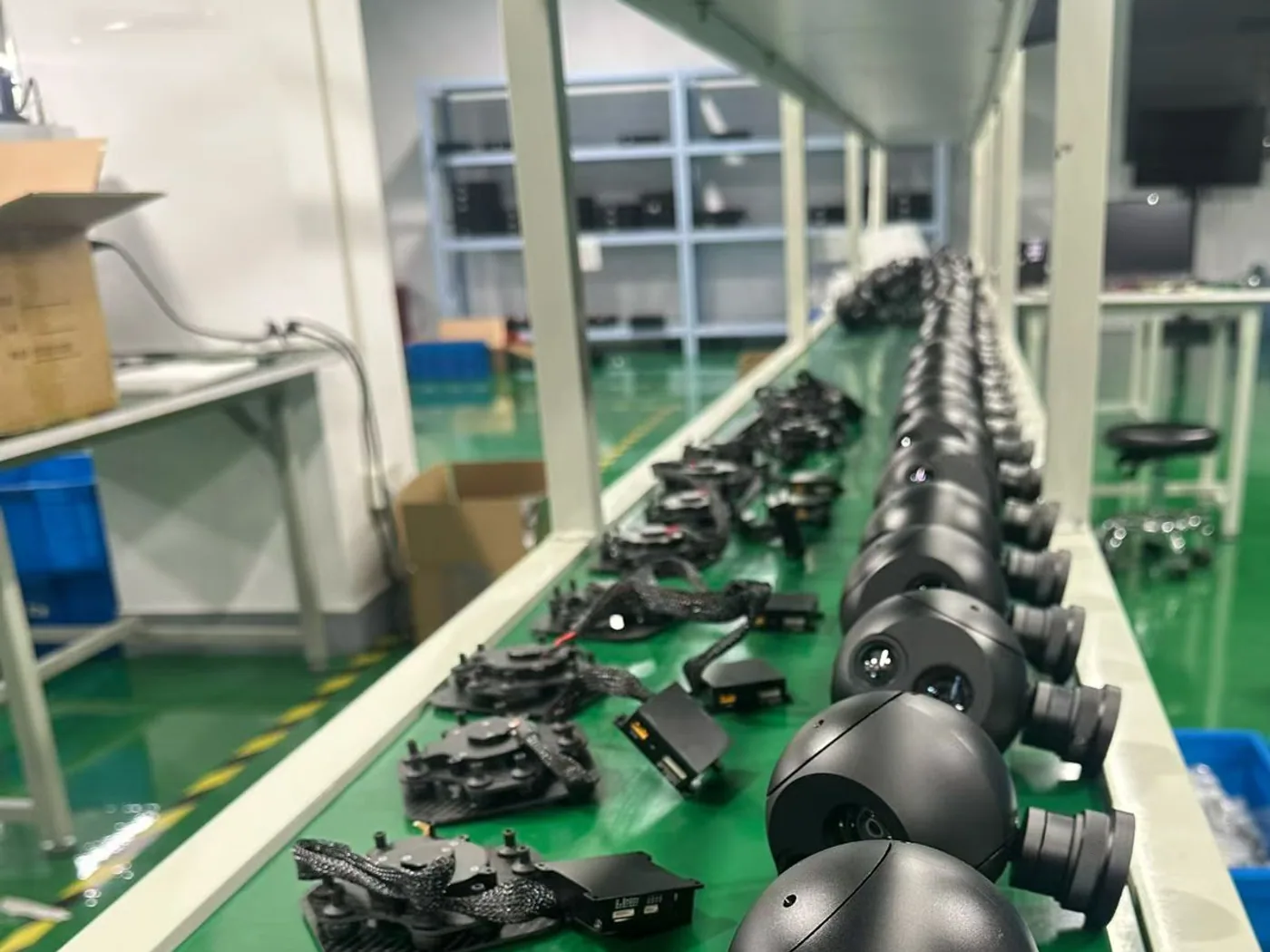
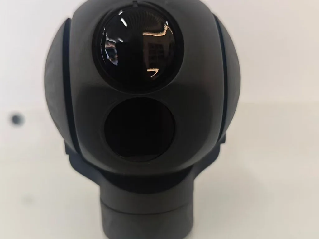
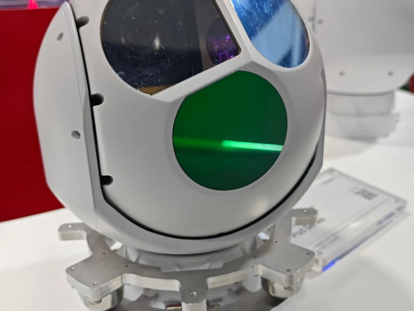
From incoming parts to a packed unit.
Seven stages, in the order a payload actually travels. Each one has an owner and a sign-off; the last two produce the paperwork that ships with the unit.
Optics and sensor sourcing
Sensors, lenses and lens mounts are selected against the specification of the configuration being built, and against the detection and identification distances the mission needs rather than against what happens to be on the shelf.
Incoming inspection
Components are checked and released to the line only once they have passed incoming inspection for the batch they arrived in. This is the stage where a supplier change gets caught, before it can reach a finished payload.
Sub-assembly
Gimbal frames, servo motors, encoders and electronic assemblies are built and bench-checked as sub-assemblies, so a fault is found at the smallest possible unit instead of at the end of the line.
Optical alignment and boresight
Visible, thermal and laser channels are aligned and boresighted to each other on the bench. On a multi-sensor head this is the step that decides whether a target seen in the thermal channel is also inside the visible-channel reticle.
Firmware and configuration
Released gimbal and servo firmware is loaded and the configuration is matched to the order — focal length, interface, mounting and coating. The reported versions are written into the inspection record for that unit.
Final inspection and test
The unit then runs the full finished-unit inspection record: operating modes, both imaging channels, recording, detection and tracking, search envelope, stabilisation accuracy, rangefinder alignment and power consumption. See the inspection criteria →
Packing and dispatch
Contents are checked against the packing list, the case is cushioned and sealed, and the calibration report and control protocol document go with the unit. Documentation for the destination market is prepared alongside the shipment.
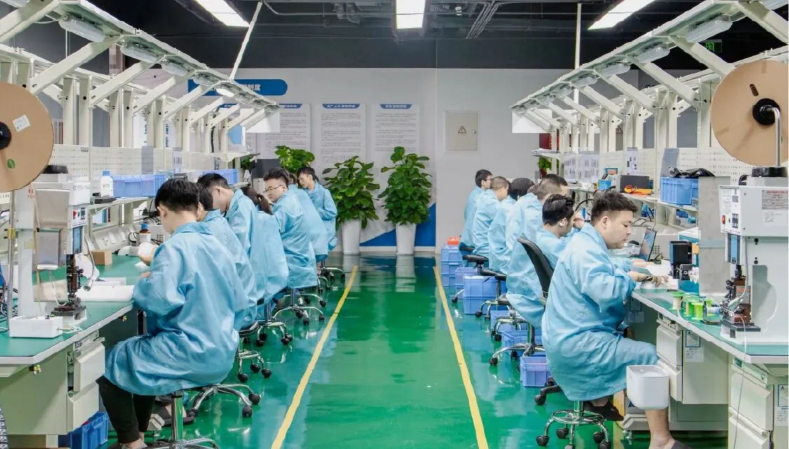
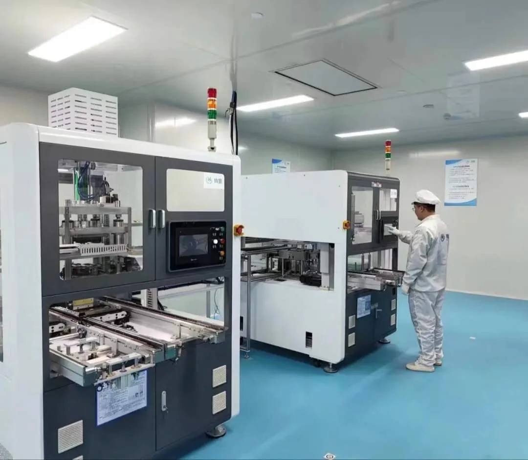
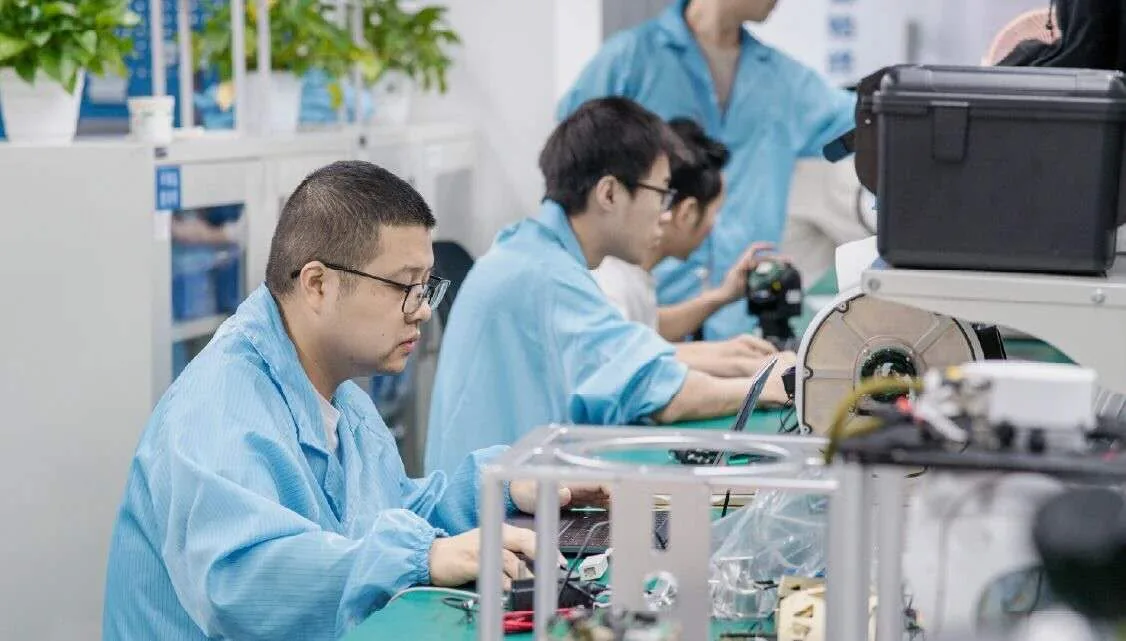
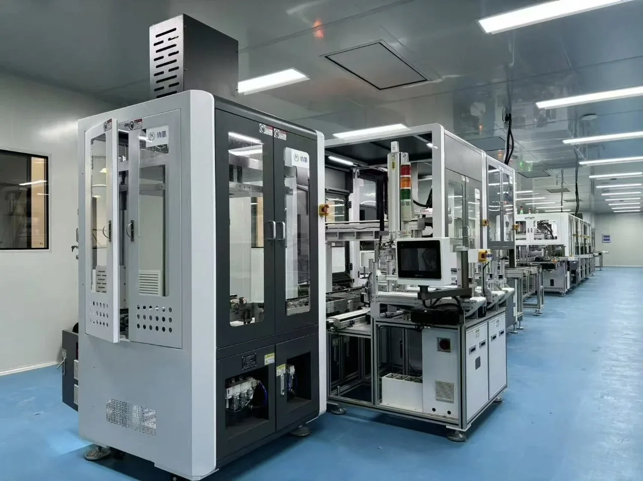
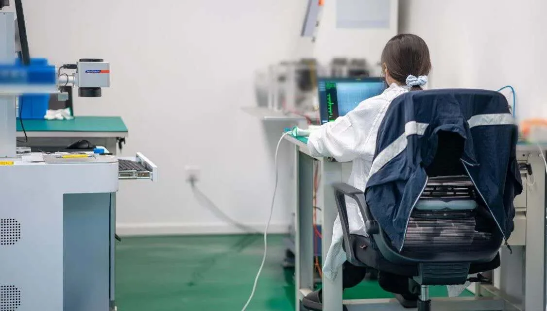
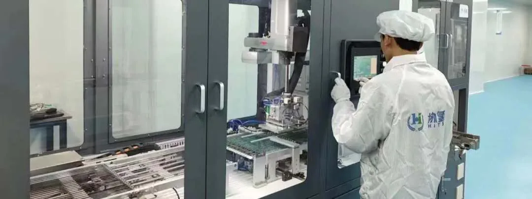
The line, the benches and the people on them.
Production, alignment and test take place in the same building, which is what makes an early engineering conversation useful: the people who answer your questions are the people who will build the unit.
The parts that decide image quality.
Two payloads can look identical in a catalogue and behave completely differently in the air. The difference lives in the parts of the design that are hardest to buy in, so those are the parts we keep.
- Optical alignment — multi-channel boresight between visible, thermal and laser paths
- Gimbal mechanics and servo hardware — direct-drive axes and encoder feedback
- Stabilisation firmware — the control loop that holds the line of sight
- AI detection and tracking module — runs on the payload, without a data link
- Payload control protocol — documented and shared so integration can start on the bench
What buyers ask before a factory visit.
Are you the manufacturer or a trading company?
We design and manufacture. Optics selection, gimbal mechanics, servo hardware, stabilisation firmware and the AI tracking module are developed in house, and assembly, calibration and test happen on our own line. That is also why an OEM request is a conversation about your platform rather than a search through a catalogue.
Can we audit the factory or visit the line?
Yes. Factory visits and supplier audits are welcome by arrangement, and they are most useful at the point where you have a specific requirement to discuss — a mounting constraint, a detection distance or a sensor combination. Tell us the platform and the mission and we will set up the right people for the visit.
Can the payload be adapted to our platform?
Yes. Because the mechanics, firmware and interface are ours, the mechanical mounting, focal length, video output and control protocol can be adjusted to the aircraft. Custom requirements start with a feasibility review against your platform constraints.
What does the process look like for a first order?
An evaluation unit is usually supplied first so the integration can be tested on the bench and in flight, with production batches scheduled afterwards. Lead time depends on the optical configuration and the quantity, and it is confirmed once the configuration is fixed.
Do you supply documentation with the hardware?
Every unit ships with a calibration and test report and a completed inspection record. The control protocol document is supplied with the first unit so your integration team can start work before the payload arrives. CE and RoHS documentation and an export compliance statement are available on request.
Bring your platform. Let us define the payload.
Share the aircraft, the mission and the imaging requirement, and we will come back with the configurations that fit.