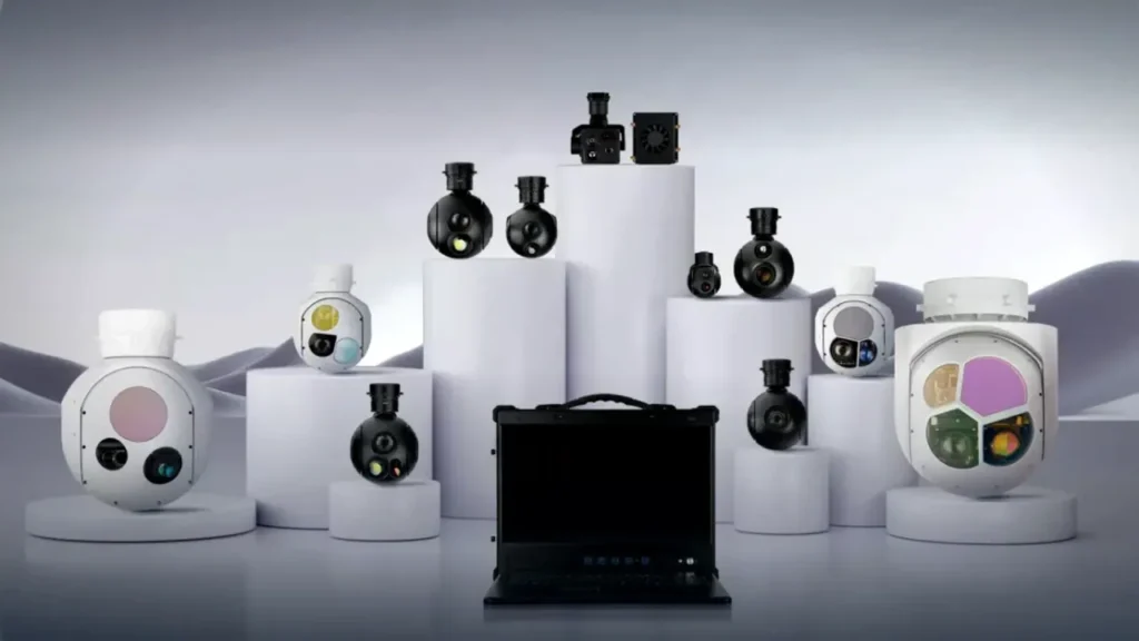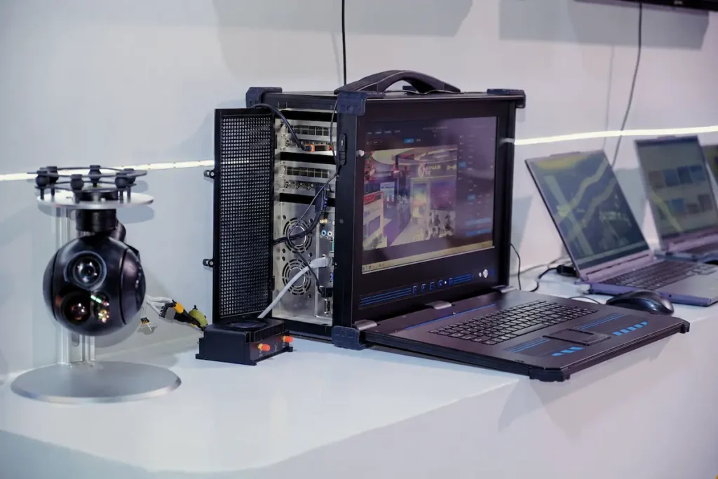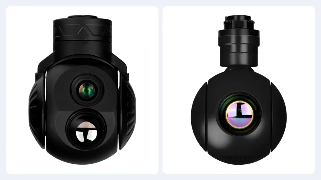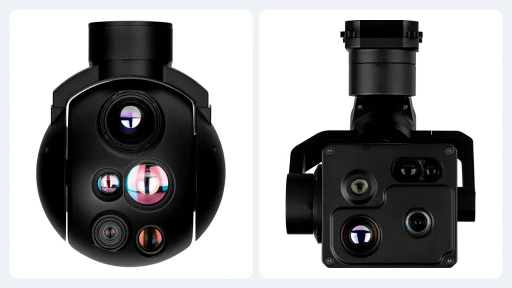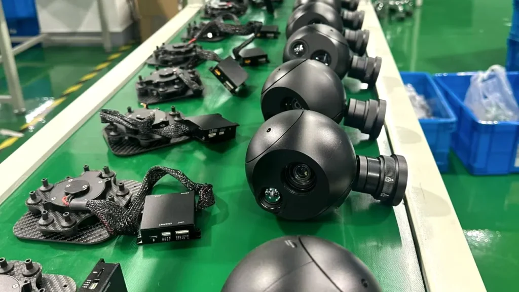
Field notes from the HITS engineering team: mission write-ups, technology explainers and payload selection guides for UAV imaging.
Read the newest material first, or use the topic cards below to move to a different part of the knowledge hub.
Knowledge hub
Payload selection, sensor choice and integration, written for UAV manufacturers, integrators and procurement teams.
From sensor choice to a flyable configuration.
A UAV imaging payload is a chain of design decisions, not a single sensor specification. Each link changes what the operator can actually see.
The camera determines what can be resolved, the lens determines the working distance, the stabilised gimbal determines whether that image stays usable while the aircraft moves, and the control link determines how quickly an operator can act on what the camera sees. These elements need to be evaluated together, because a strong headline specification can still produce a weak operational result when the rest of the chain is not matched to the mission.
This section looks at the technical choices behind that chain. It explains how visible-light, thermal and dual-sensor EO/IR channels differ in daylight, low light and obscured conditions; how optical zoom, field of view, detector resolution and laser rangefinding affect detection and recognition; and why two-axis and three-axis stabilisation suit different aircraft and operating profiles. It also covers onboard AI, video latency and the interfaces that connect the payload to the flight controller and ground station.
For UAV manufacturers and system integrators, the useful outcome is not the longest specification sheet but a shortlist that can be tested on the bench and then in flight. The articles below compare payload classes against real constraints, highlight the questions worth asking a supplier, and show where a measurement or a test report matters more than a marketing claim.
Use the technical guides to build a payload brief, then compare the relevant EO camera, thermal camera and EO/IR gimbal configurations against the aircraft, range and deadline for evaluation.
• 01 Sensors and channels: EO, thermal and EO/IR choices, detector formats and low-light performance.
• 02 Optics and range: Zoom, field of view, resolution and laser rangefinding.
• 03 Stabilisation: Two-axis and three-axis gimbals, tracking and vibration.
• 04 Integration: MAVLink, video links, latency and onboard AI.
Define the imaging task before comparing hardware
A useful comparison starts with three questions: what must be seen, at what distance, and what decision will the operator make from the image? Detection, recognition and identification require different amounts of detail. A thermal spot that reveals a person at 900 m may still be too small to identify clothing or equipment. A daylight camera that reads a label at 200 m may not hold a moving vehicle steady at 1,500 m. Separating these levels prevents a headline resolution or zoom figure from being mistaken for mission performance.
The next step is to describe the scene. Target contrast, background clutter, haze, spray, dust, low light and vibration all reduce the useful range of a payload. A specification measured against a high-contrast test target in clear conditions is not a promise of the same result over water, against vegetation or through a city at dusk. Ask for sample imagery or recorded test conditions that resemble the intended mission.
Read the optical chain as one system
Detector resolution, pixel pitch, focal length, field of view and image processing determine how much detail reaches the operator. Optical zoom changes the field of view through the lens; digital zoom enlarges pixels that are already present. The two are not interchangeable. A narrow field of view can improve identification at distance but makes the initial search slower and increases the effect of aircraft movement. A wider view supports situational awareness but may leave a small target spread across too few pixels.
Thermal performance follows the same logic, with additional variables. Detector format, lens aperture, pixel pitch, NETD, frame rate and the scene’s temperature difference all affect what appears on screen. A higher-resolution thermal core can reveal more detail when the lens and processing support it, but it also increases data volume, power demand and cost. The right choice depends on the target, the range and whether the output is used for observation, measurement or automated detection.
Stabilisation, latency and integration belong in the same test
An image that looks sharp on a bench can become unusable in flight if the gimbal cannot reject vibration or hold a line while the aircraft turns. Two-axis and three-axis heads solve different problems, and the mounting, centre of gravity and airframe stiffness influence the result. Video encoding, link bandwidth and ground-station processing add latency that affects how quickly an operator can follow a moving target or correct a track.
Onboard AI adds another layer. Detection, classification, recognition and tracking are separate capabilities and should be tested separately. Ask where inference runs, what happens when the link degrades, how a track is acquired and released, and whether the operator can always override the automation. A transparent failure mode is more valuable than an optimistic accuracy claim.
Build a test that reflects the mission
A useful evaluation moves from the bench to a representative flight profile without changing several variables at once. Begin with the camera fixed and the aircraft powered down: confirm the firmware, video format, control commands and recording path. Then mount the payload on the aircraft and repeat the checks with the engines or motors running, because vibration and electrical noise can expose problems that a bench test never shows. Record the image at wide, medium and full zoom while the aircraft yaws, climbs and turns.
Compare the result at the range and target size that matter for the mission, not only at the closest, most favourable distance. Note the light, weather, background and amount of image processing applied. If a supplier provides sample footage, ask for the original file rather than a re-encoded social-media clip, and check whether the recording was made with the same lens, detector and firmware that will ship. A repeatable test record is more useful than a single impressive image.
Use these explainers as a technical checklist
Each article in this category isolates one part of the chain so that a specification can be examined without losing sight of the aircraft and the mission. Use them to prepare a bench test, challenge a supplier’s evidence or decide which measurement is missing from a quotation. When the shortlist is ready, compare the relevant EO camera, thermal camera and EO/IR gimbal configurations, or request a payload consultation for a review against the airframe and operating profile.
Payload decisions touch mission design, optics, airframe integration and procurement. Choose the topic that matches the decision in front of you, or follow the category links into the technical detail.
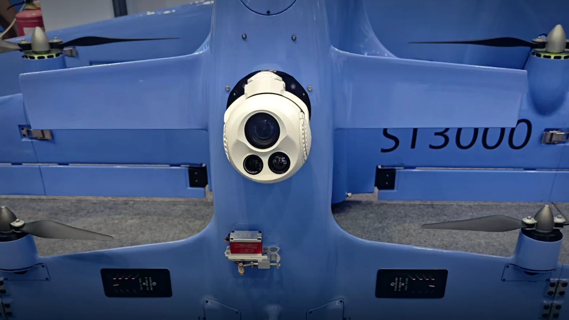 Applications1 article
Applications
Mission profiles, operating environments and payload trade-offs for inspection, patrol, search and survey work.
Explore topic →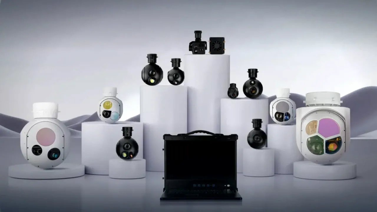 Technology5 articles
Technology Explained
Sensors, optics, stabilisation, video links and onboard AI explained for UAV engineering teams.
Explore topic →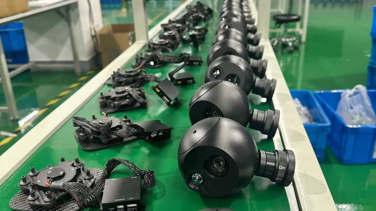 Guides5 articles
Buying & Integration Guides
Procurement, supplier evaluation, integration and flight-test checklists for UAV programmes.
Explore topic → News2 articles
News & Projects
Manufacturing, product development and field updates from across HITS.
Explore topic →Share the platform, mission and constraints. HITS can compare EO, thermal and EO/IR options, then confirm the integration details that shape the shortlist.
WhatsApp us