A 40x camera isn’t automatically better than a 30x one, and a 3 km laser rangefinder doesn’t mean you can identify anything at 3 km. Those two sentences save more procurement mistakes than any datasheet comparison, and this article is the explanation behind them.
Long-range payloads get sold on three numbers: zoom ratio, focal length and rangefinder range. Those three describe three completely different things. Mixing them up is how an aircraft ends up with a payload that measures distance beautifully and can’t read a rating plate.
So let’s take them one at a time, with the arithmetic shown, and finish with the questions worth putting in an RFQ.
What a long-range gimbal camera actually is
Long range is a job description, not a specification
A long-range UAV gimbal camera is a stabilised imaging payload built to observe something at a distance. That’s the whole definition, and it’s deliberately vague, because “long range” means different distances for different jobs.
A camera that gives you a useful look at a 60 m transmission tower from 150 m away may be useless for reading a serial number on a junction box. Both are “long range” in a brochure. The only definition that holds up is the one your mission writes: the smallest thing you have to see, and how far away it will be.
Typical civilian work in this category includes power line and substation inspection, offshore and coastal observation, large industrial site surveys and environmental monitoring. The distances vary enormously across those jobs, so don’t let anyone, including us, sell you a payload on the phrase alone.
The parts that actually decide the picture
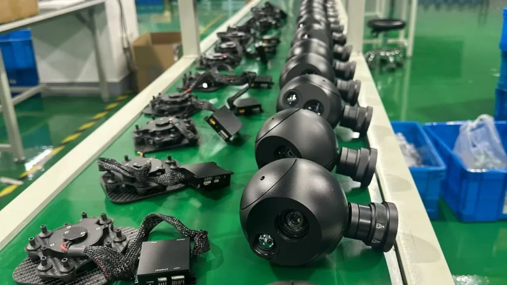
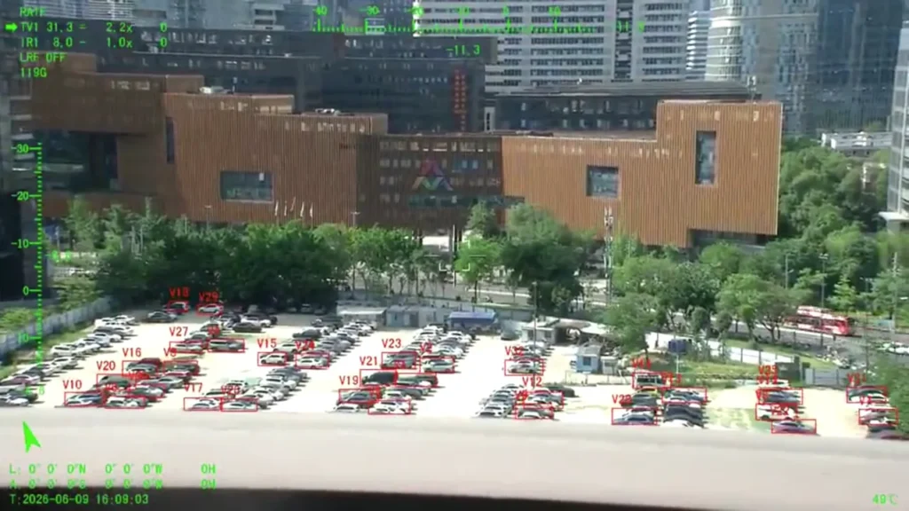
A payload is an image sensor, a lens, a stabilisation mechanism, a controller and a video path. In many configurations there’s also a thermal channel, a laser rangefinder, and onboard processing running on the imagery.
Every one of those can cap the result. A superb long lens is worth nothing if the stabilisation can’t hold the line of sight steady, if the focus hunts, or if the downlink can’t carry the detail the lens just produced. This is why the same payload can look excellent on one aircraft and disappointing on another [2].
EO, IR or both
An EO (electro-optical) channel is your visible-light camera: surface detail, colour, markings, and a good zoom range in decent light. An IR channel shows received infrared radiation instead. No illumination required, and often more useful than visible light when you’re looking for heat rather than appearance.
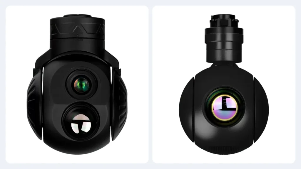
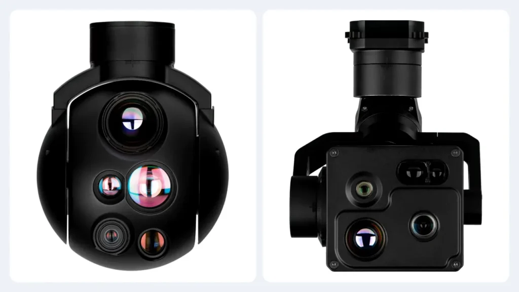
A combined EO/IR payload carries both on one stabilised cage, which matters because it means the two channels point at the same thing without the aircraft moving. Adding the thermal channel should be justified by the inspection though: if nobody on the project needs a heat signature, it’s weight and money for nothing.
Optical zoom: what the number on the box actually means
Optical zoom versus digital zoom
Optical zoom moves glass. It changes the focal length, which changes how much of the scene lands on the sensor. Detail that was always there occupies more sensor pixels afterwards.
Digital zoom crops and enlarges what the sensor already recorded. It’s genuinely useful for the operator, since a bigger picture on the screen is easier to read, but it can’t create optical detail that was never captured. When you compare payloads, make sure you’re comparing optical numbers to optical numbers, and treat software enlargement as what it is: a display convenience, not a performance figure.
Zoom ratio is a range, not a reach
The ratio on the box is simply the longest focal length divided by the shortest:
optical zoom ratio = maximum focal length ÷ minimum focal length
Here are three configurations from our own range, so you can see what the ratio is actually describing [2]:
| Configuration | Focal length | Zoom ratio |
|---|---|---|
| HQ-100D visible channel | 4.7 – 47 mm | 10x |
| HQ-115D and HQ-115T visible channel | 4.3 – 129 mm | 30x |
| HQ-115S and HQ-135T visible channel | 4.25 – 170 mm | 40x |
Read that table carefully and you can see the trap. The ratio tells you how much the lens can change. It says nothing at all about how far you can see, because two lenses with completely different reach can carry the same ratio.
Why the ratio alone cannot rank two cameras
Two lenses, both hypothetical, both real designs:
- Lens A: 4 – 120 mm, which is 30x.
- Lens B: 10 – 150 mm, which is 15x.
Lens B has half the ratio and a longer reach. On the same sensor it will put more detail on a distant target than Lens A, despite the smaller number on the front of the box. Anyone ranking those two by zoom ratio would have picked the wrong one.
What you actually need to compare is the focal length range, the sensor and its resolution, the field of view each focal length produces, and the optical quality of the glass. The ratio is a summary, and summaries lose information.
The cost of a longer lens
Long focal length isn’t free. The same small movement of the aircraft displaces a much larger part of the scene, so every bit of residual jitter, vibration and focus error is magnified along with the image. A long lens also gathers more atmosphere along the line of sight, which matters over water and in humid or hazy conditions.
That’s why the honest way to buy a long-range payload is as a complete optical and stabilisation system, not as a lens specification. Our own heads hold line-of-sight accuracy to 100 microradians or better, and that number is doing as much work in the final image as the focal length is [2].
Field of view: the number that actually tells you what you will see
What field of view is
Field of view is how much of the world the camera takes in. It can be written as an angle, or, more usefully for inspection work, as the physical width of the scene at a stated distance.
A wide field of view covers a lot of ground and spends few sensor pixels on any one thing inside it. A narrow field of view covers less ground and concentrates the pixels. That’s the entire trade, and no lens escapes it.
The arithmetic, if you want it
Angular field of view depends on the sensor dimension and the focal length [1]:
horizontal FOV = 2 × arctan( sensor width ÷ (2 × focal length) )
For distant targets there’s a shortcut that’s easier to use at a desk, because the small-angle approximation holds well enough to plan with:
scene width ≈ distance × sensor width ÷ focal length
Take a camera with a 6.4 mm wide sensor, looking at a structure 100 m away:
| Specification | Configuration A | Configuration B |
|---|---|---|
| Sensor width | 6.4 mm | 6.4 mm |
| Focal length | 32 mm | 64 mm |
| Observation distance | 100 m | 100 m |
| Approximate scene width | 20 m | 10 m |
| Ground covered by one horizontal pixel (1,920 px) | 10.4 mm | 5.2 mm |
Doubling the focal length halves the scene width. Nothing else changed: same sensor, same aircraft, same distance. And yet the target is now described by twice as many pixels in each direction.
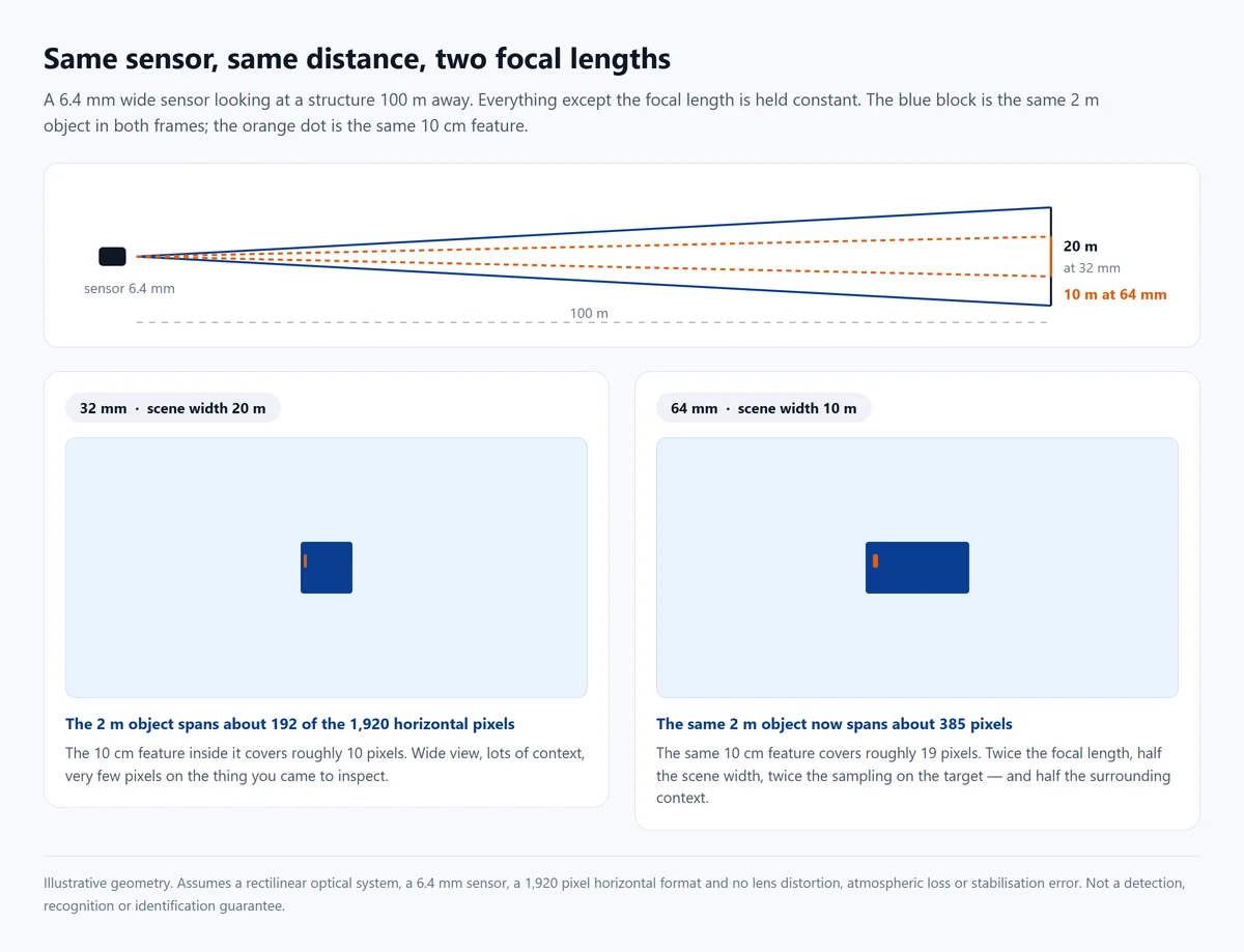
Treat this as geometry, not as a promise. The calculation assumes a rectilinear optical system with a 6.4 mm sensor and no lens distortion, atmospheric loss or stabilisation error. It shows how sampling scales with focal length. It isn’t a detection, recognition or identification guarantee, and it isn’t a claim about any specific camera’s image quality.
Wide or narrow: pick one, then plan around it
Wide angle is what you want for finding the site, holding a large structure in frame, and documenting context around a problem. Narrow angle is what you want when the inspection depends on a small feature.
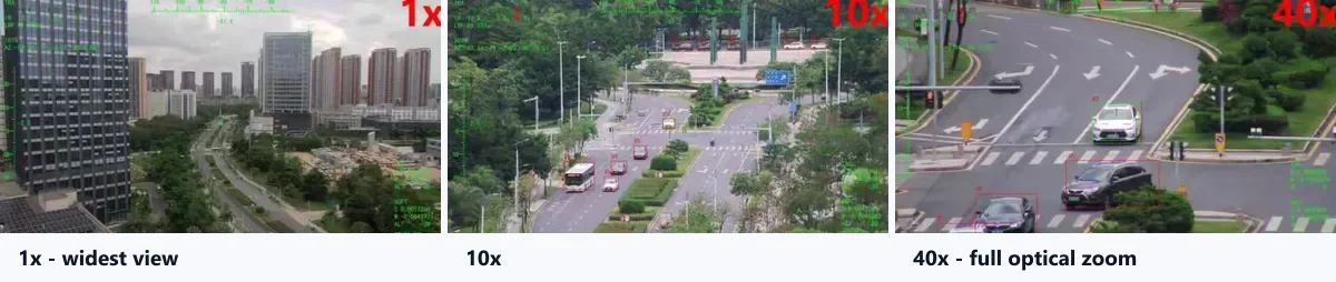
A zoom camera lets you do both on one flight, which is the practical reason long-range payloads are built this way. The catch is that the two ends of the zoom range don’t perform equally. The long end places far more demands on stabilisation, focus and the atmosphere, so the useful detail at 40x isn’t simply 40 times the detail at 1x.
Our advice for any project is to state both halves of the requirement: the scene you have to cover, and the smallest feature you have to see inside it. If nobody can name the smallest feature, the specification isn’t finished yet.
Detection, recognition and identification are three different jobs
The three levels
Anyone who has bought optics for security work will recognise these terms, and they’re worth borrowing for UAV inspection:
- Detection: establishing that something relevant is present.
- Recognition: working out the general category it belongs to.
- Identification: resolving the specific detail the task depends on.
They aren’t three points on one scale so much as three different questions, and the gap between them is where most disappointment in long-range procurement lives. Spotting a hot connection on a pylon is detection. Knowing it’s a connector rather than a bird is recognition. Reading the corrosion pattern on the fitting is identification, and only the third one produces an inspection finding.
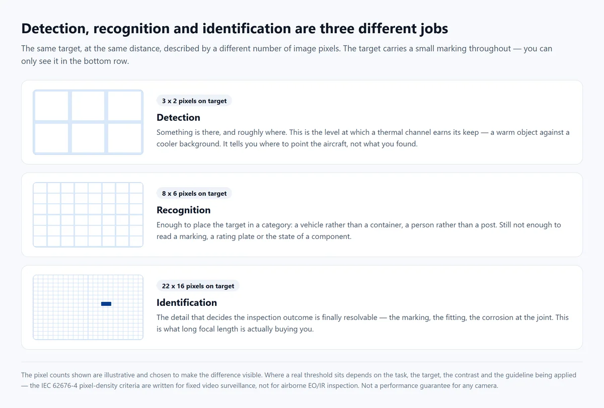
The Axis whitepaper on pixel density is a good place to see how these levels are defined for video systems [3]. One caution before you build a specification on it: those criteria were written for fixed surveillance cameras with a known installation, not for airborne EO/IR payloads. They’re guidelines rather than performance guarantees. They’re useful for framing the question, not for settling a procurement argument.
One more thing about the levels, because it comes up constantly: they depend on the target, not just the camera. A 2 m vehicle and a 10 cm connector at the same distance land on very different numbers of pixels. Ask any supplier to demonstrate the level you need on a target of the size you actually have.
Why the test conditions matter more than the claim
Image quality depends on a long list of things that travel with the aircraft rather than the camera: the size and contrast of the feature, the lighting or thermal contrast, haze, humidity, turbulence, platform movement, and whatever processing is applied on the way to your screen.
A capability measured in a clear-weather laboratory isn’t the same capability over a humid coastline. So a useful performance statement has to name the configuration, the lens setting, the target, the distance, the conditions and the evaluation method. Anything less than that isn’t a specification, it is a slogan, and “long-range HD imaging” is the classic example.
What a laser rangefinder in a gimbal camera really measures
The principle, in one paragraph
A laser rangefinder fires a short pulse of light at whatever the beam is aimed at, and times what comes back. Halve the round trip, divide by the speed of light, and you have a distance. Some modules modulate a continuous beam and measure the phase shift instead, which is the same idea in different electronics.
What matters commercially isn’t which method sits inside the housing. It’s that the rangefinder answers exactly one question: how far away is the spot the beam landed on, and that answer is produced independently of what the camera can see. An LRF adds distance information to an imaging payload. It doesn’t add a single pixel of image detail.
The three specifications hiding behind one range figure
Measurement range
Rated range is published as a minimum and a maximum, and both ends carry information. In our own range the HQ-115T is published from 5 m to 1.5 km, and the HQ-125TB, HQ-135T and HQ-135TA from 15 m to 3 km, at plus or minus 1 m [2][6][7].
The minimum exists because a strong return from a close surface can overwhelm the receiver. The maximum isn’t a wall either. It’s a distance the module is designed to reach against a target that returns enough light. Reflectivity, surface angle, target size, the atmosphere in between and the module design all move the real result. A rated 3 km measured against a cooperative target in clear air can behave quite differently against dark, wet, oblique equipment. The useful question in an RFQ is what target and what conditions the figure was established against.
Measurement accuracy
Accuracy is how close the reported number is to the truth under stated conditions. It’s a separate specification from range, and separate again from repeatability, whether the same target produces the same answer twice in a row.
For inspection work, two questions are worth asking: does the stated accuracy hold across the whole operating range, or only in the middle of it? And how does the module behave when the return is weak? A figure that’s honest at 200 m and optimistic at 3 km is worth knowing about before a workflow is built on top of it.
Laser safety classification
This one is a compliance requirement rather than a feature to compare. IEC 60825-1 is the framework that classifies laser products and sets out the safety information and labelling that belongs with each class [4]. The FDA’s laser guidance explains how those classes reflect different hazard levels, and why viewing aids can change the exposure picture [5].
So when you evaluate a rangefinder, ask for the actual classification and the supporting documentation for the module in the configuration you’re buying. A wavelength, a power figure, or the phrase “eye-safe” on its own doesn’t replace a classification document, and a supplier shouldn’t offer it as if it did.
Two more items belong on the same page: who’s permitted to operate the system around people and other aircraft, and whether the destination country adds its own import or end-use requirements. Both are far easier to settle before an order than after one.
Where a rangefinder earns its place
Distance measurement is genuinely useful when the number is part of the deliverable. That covers stand-off measurement to a structure you can’t approach, recording where along a line an anomaly sits, sizing a scene, aiming a narrow field of view with confidence, and feeding a mapping or photogrammetry process.
One caution on that last one. A rangefinder reports the distance from the aircraft to a point on a surface. Turning that into survey-grade coordinates also needs the aircraft’s own position and orientation, system-level calibration and a validation step. Survey accuracy is a property of the whole system, not of the laser module, and it shouldn’t be assumed to arrive with the rangefinder.
Why a 3 km LRF is not a 3 km camera
Here’s the sentence worth carrying into a procurement meeting: the rangefinder and the camera are two instruments that happen to share a housing.
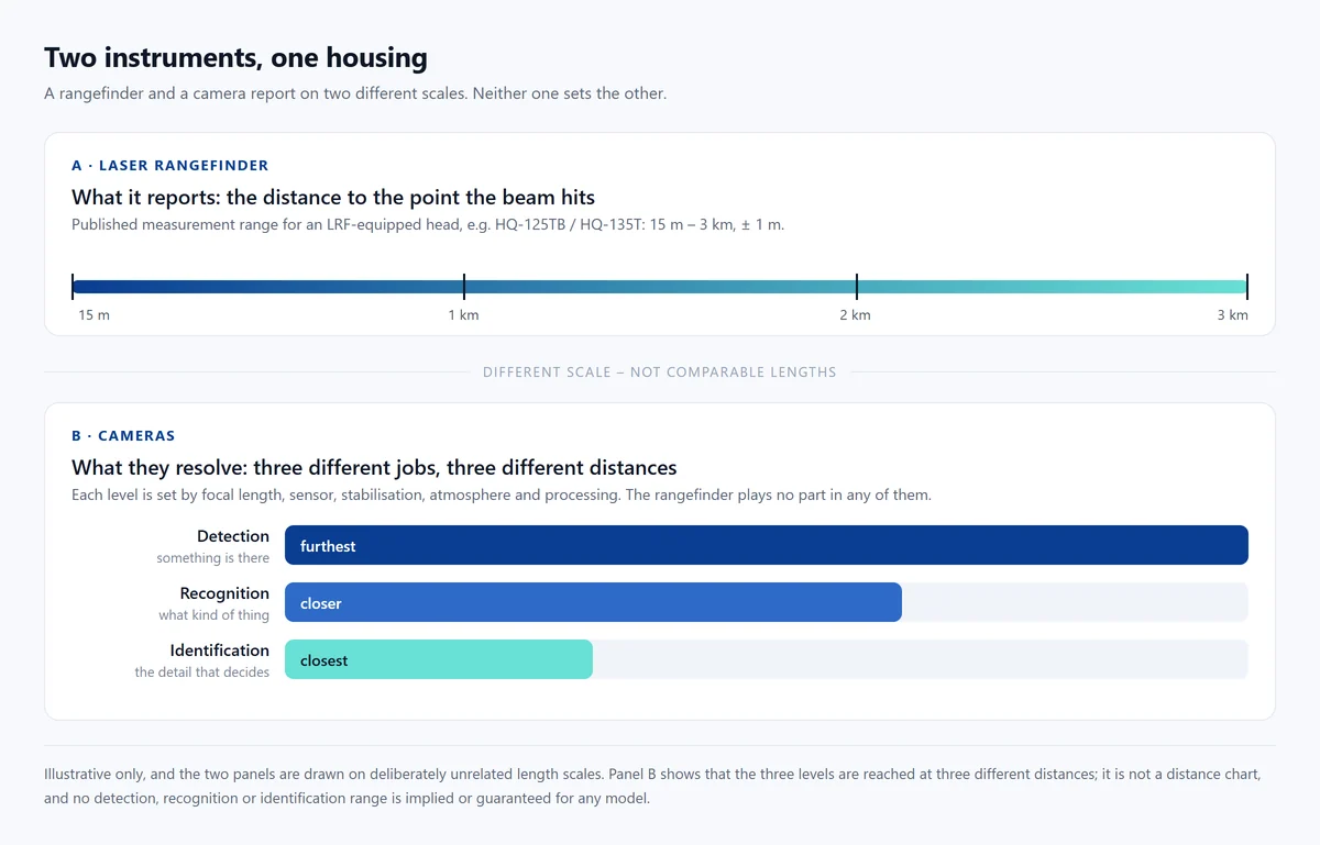
Suppose a module is rated to 3 km. That tells you the rangefinder can produce a distance to a suitable target at that range under its stated conditions. It tells you nothing about whether the EO or IR channel produces an image at 3 km in which a particular feature is resolvable. That’s set by focal length, sensor, stabilisation, atmosphere and processing, all of it covered above.
The reverse mistake is just as common: assuming a long lens makes the rangefinder unnecessary. A 40x view still has to be pointed at the right object, and the distance reading is often the only way to know that it’s.
Choosing between long-range gimbal camera configurations
EO-only zoom payloads
If the work happens in daylight and nobody on the project needs a heat signature, an EO-only head is usually the right answer. Fewer channels means less to go wrong, less mass on the mount, less power to find and less money spent on a capability that won’t be used.
The HQ-115S is the example in our own range: a 40x visible-light channel covering 4.25 mm to 170 mm, no thermal channel and no rangefinder, at 1 kg or under [2]. It delivers the longest reach of the EO-only heads while staying inside the mass budget of a small multirotor.
EO/IR payloads for work that changes conditions
Adding a thermal channel to the same stabilised cage means both views are pointed at the same object without moving the aircraft, and that matters when you need the visible-light answer and the thermal answer for the same finding.
The HQ-115D pairs a 30x EO channel (4.3 mm to 129 mm) with a 640 x 512 thermal channel on a 25 mm lens, at 1 kg or under [6]. That combination suits inspection programmes where surface detail and heat both carry meaning: substations, process plant, rotating equipment, and buildings whose thermal behaviour is part of the deliverable.
Adding the thermal channel should still be justified by the inspection. If the report will never contain a heat reading, the thermal channel is weight and money. EO vs IR vs EO/IR goes through that decision properly.
Configurations with an integrated rangefinder
The distance-measuring heads in the HQ series share the same EO and IR optics philosophy and add an LRF to the same housing. The choice between them is mostly about which focal length and which thermal lens the mission needs.
| Model | EO channel | Thermal channel | Published LRF | Weight |
|---|---|---|---|---|
| HQ-100D | 10x, 4.7 – 47 mm | 640 x 512, 19 mm lens | None | ≤ 800 g |
| HQ-115S | 40x, 4.25 – 170 mm | None | None | ≤ 1 kg |
| HQ-115D | 30x, 4.3 – 129 mm | 640 x 512, 25 mm lens | None | ≤ 1 kg |
| HQ-115T | 30x, 4.3 – 129 mm | 640 x 512, 25 mm lens | 5 m – 1.5 km, ± 1 m | ≤ 1 kg |
| HQ-125TB | 30x, 4.3 – 129 mm | 640 x 512, 35 mm lens | 15 m – 3 km, ± 1 m | ≤ 1.2 kg |
| HQ-135T | 40x, 4.25 – 170 mm | 640 x 512, 35 mm lens | 15 m – 3 km, ± 1 m | ≤ 1.4 kg |
Read down the EO column and the two longest lenses aren’t on the heaviest heads. Read across the mass figures and the difference between the lightest and heaviest configuration in the table is about 600 g. On a small multirotor that’s endurance, not a rounding error.
Source and scope of that table: manufacturer-published three-axis specifications for the HQ range [2][6][7]. It shows published configuration differences rather than independently verified imaging or measurement performance. Focal lengths, thermal lenses, rangefinder ranges and masses should be confirmed against current documentation before an order, and laser documentation requested separately.
Two lessons fall out of the table. An aircraft that needs 40x visible-light zoom doesn’t thereby need a thermal channel or a rangefinder. The HQ-115S exists for exactly that requirement. And a project that needs thermal observation and distance measurement has to compare complete sensor configurations, because zoom ratio on its own won’t get anywhere near the decision.
Balancing optics, weight and power
Long-range payload selection is a trade between optics, mass, power, stabilisation and cost, and the trade is usually decided by the airframe rather than by the camera.
A heavier head can carry more capability, but it takes endurance and payload margin with it, and it may push the mount, the gimbal clearances and the power budget into a redesign. Connector count and cable routing for an additional channel matter too. The configuration that wins is the one that meets the imaging requirement without adding anything the mission has no use for, and that’s a smaller set of options than most datasheets suggest. If the payload and airframe questions overlap on your project, the integration guide covers mounting, power, control and video testing in order.
How to compare long-range gimbal camera specifications
Compare focal length and sensor, not the ratio
Ask for the minimum and maximum optical focal length, the sensor resolution and its active dimensions, the horizontal and vertical field of view, and the focus characteristics. Those five answers let you place any two cameras on the same footprint and see which one actually puts more detail on your target [1].
Manufacturers publish different things on zoom, and some of the numbers mixed into those sheets aren’t optical at all. Software enlargement, digital crop, or an enhanced display mode. Keep optical figures on one side of the page and everything else on the other.
Ask for image samples at known distances
Original stills and video, with the distance, target size and conditions recorded, turn a photograph into evidence. Two samples without that information can’t be compared at all. The closer one will simply look better.
Samples should be of the kind of feature your inspection actually depends on. A dramatic image of a large vehicle at 2 km doesn’t answer the question of whether a 10 cm fitting is resolvable, and the two are different purchases.
We publish detection distances for the HQ range against a 1.7 m person and a 2.3 m vehicle, which is the convention most of this industry uses [2]. Treat those as detection figures under stated conditions. Detection is the first of the three levels, and it isn’t the same claim as recognition or identification, which is why we’d rather show you frames than quote you a range.
Check the stabilisation and the video path
Video samples should include aircraft movement and vibration, because a long lens magnifies every bit of residual jitter along with the scene. Lab footage on a bench establishes very little about airborne performance.
Alongside that, confirm the native video resolution, frame rate, codec, onboard recording, and whether the output interface matches your airframe and downlink. The sharpest optics in the range are wasted if the video path can’t carry what the lens produced [2]. If the mount itself is still an open question, two-axis vs three-axis gimbal cameras covers which configuration holds which job.
Confirm the rangefinder and its documentation
For any distance-measuring configuration, put these on the checklist before the comparison starts:
- Whether the selected model includes an LRF at all.
- Published minimum and maximum measurement distances, and the target and conditions behind them.
- Measurement accuracy, and whether it’s stated across the whole range.
- Laser safety classification and the supporting documentation for that module.
- Electrical and software integration requirements.
- Export and destination-country import requirements for the configuration and the end use.
None of those are negotiating points. They’re either documented or they’re open questions, and an open question about a laser classification isn’t something to leave until after the purchase order.
Long-range gimbal camera procurement checklist
A structured RFQ gets you comparable answers instead of a brochure. Two tables do most of the work: one about your aircraft and mission, one about the hardware documentation you expect back.
Mission and platform first
Suppliers can’t recommend a configuration sensibly without these. Filling them in before you send the enquiry shortens the whole process.
| Item | What to write down |
|---|---|
| Smallest feature | The smallest thing the inspection must resolve, and whether you need to detect, recognise or identify it |
| Distance | Typical and worst-case stand-off distance to that feature |
| Conditions | Daylight, low light, thermal contrast expected, over water or inland, typical humidity and haze |
| Aircraft | Type, maximum payload mass, available power, mounting location and clearances |
| Interfaces | Flight controller, control protocol and video output you need to match |
| Deliverable | Images, video, or a measured number, and whether the number is a distance or a temperature |
Long-range optics shouldn’t be selected before that platform budget is known, because the answer to “can we fit the 40x head” is an aircraft question rather than a camera one.
Documents and testing to ask for
| Procurement item | Information to request |
|---|---|
| EO optics | Focal length range, sensor dimensions, resolution and field of view |
| Thermal channel | Resolution, thermal lens, sensitivity and whether measurement functions are included |
| Gimbal | Stabilisation specification with the conditions it was established under |
| LRF | Range, accuracy, laser classification and the supporting documentation |
| Integration | Mounting drawings, power requirements, control and video interfaces |
| Testing | Original image samples and representative flight footage with recorded conditions |
| Commercial | Sample availability, lead time, warranty and support arrangements |
Send the same two tables to every supplier. It’s the fastest way to find out which ones are answering your questions and which ones are quoting a zoom number at you.
Frequently asked questions
Is 40x optical zoom always better than 30x?
No. The ratio describes how much the focal length changes between the widest and narrowest setting, not how much detail reaches a target. A camera’s useful long-range detail also depends on its maximum focal length, sensor size, optical quality, stabilisation and the conditions you fly in. Two lenses can carry the same ratio and have completely different reach.
What’s the difference between optical and digital zoom?
Optical zoom changes the focal length and the field of view, so a smaller part of the scene lands on more sensor pixels. Digital zoom enlarges part of the image the sensor already recorded. It makes the picture easier to look at, and it doesn’t create any new optical detail. When you compare two payloads, keep optical figures on one side of the page and software enlargement on the other.
Does a 3 km laser rangefinder mean the camera can identify objects at 3 km?
No, and the two numbers aren’t related. The rangefinder reports distance to a suitable target under its stated measurement conditions. Whether the EO or IR channel produces an image at that range in which a specific feature is resolvable is a separate question, answered by focal length, sensor, stabilisation, atmosphere and processing. Measure the ranging performance and the imaging performance separately, and ask for the test conditions behind both.
How does stabilisation affect long-range imaging?
A longer focal length magnifies platform movement along with the scene, so the same residual jitter that’s invisible at the wide end becomes obvious at full zoom. A stabilised gimbal holds the viewing direction, but the result in the final frame also depends on vibration isolation, the aircraft’s own behaviour and the control loop. Representative flight footage is the evidence worth asking for; bench footage is not.
What to take away
Zoom ratio, focal length and rangefinder range are three different measurements, and only one of them describes the picture you’ll get. The ratio tells you how much the lens can change. The focal length, against your sensor, tells you how much of the scene covers how many pixels. The rangefinder tells you how far away something is, without saying anything about how well you can see it.
So define the mission before comparing anything: the smallest feature, the distances, the conditions, and whether the answer you need is an image or a number. Then compare complete configurations on optical focal length, sensor, field of view, stabilisation and documented LRF behaviour, and ask for original samples with the distances recorded.
If there’s one habit worth keeping from this article, it’s asking what conditions a figure was measured under. It’s the question that separates a specification from a slogan, and the answer usually tells you more about the supplier than the number does.
References and technical sources
- [1] Edmund Optics – Understanding focal length and field of view. The relationship between sensor size, focal length, angular field of view and working distance.
- [2] HITS – Three-axis gimbal cameras. Manufacturer-published specifications for the HQ-100D, HQ-115S, HQ-115D, HQ-115T, HQ-125TB, HQ-135T and related configurations.
- [3] Axis Communications – Pixel density based on IEC 62676-4:2014. Detection, observation, recognition and identification, with pixel-density guidelines by application.
- [4] International Electrotechnical Commission – IEC 60825-1:2014. Safety of laser products, equipment classification and requirements.
- [5] U.S. Food and Drug Administration – Frequently asked questions about lasers. Laser hazard classification, labelling and optical safety considerations.
- [6] HITS – HQ-115D three-axis gimbal camera. Manufacturer-published 30x EO/IR configuration, including its 640 x 512, 25 mm thermal channel and the LRF variant built on the same optics.
- [7] HITS – HQ-135TA three-axis EO/IR gimbal camera. Manufacturer-published EO/IR configuration with an integrated 3 km laser rangefinder.
Technical note: HITS product figures are manufacturer-published specifications, not independent comparative test results. The field-of-view worked examples above are illustrative geometry and shouldn’t be read as verified operational imaging distances. Image quality, stabilisation performance, rangefinder behaviour, laser safety classification and export eligibility are configuration and destination specific, and must be confirmed against current technical documentation before procurement.
Request long-range gimbal camera specifications and image samples
Tell us the smallest feature you have to see, the distance you have to see it from, and whether the project needs thermal imaging or distance measurement. We’ll come back with the configuration that fits, and tell you plainly if the 40x head isn’t the one you need.
Related reading: the gimbal camera range as a whole, the three-axis heads that most long-range configurations are built on, and the EO/IR payload range. If you’re still choosing the sensing channel, EO vs IR vs EO/IR covers that decision; how to choose an industrial UAV gimbal camera covers the payload as a whole; two-axis vs three-axis covers the mount; and 640 x 512 vs 1280 x 1024 covers the thermal detector question that sits behind the IR column above.