Fitting a gimbal camera to a drone looks like a mounting job. It isn’t. It’s an integration project, and the camera is only one of the subsystems that has to agree with the others.
Most of the work happens in four places: the mechanical interface, the power and data wiring, the control protocol, and the video path down to the ground station. Get all four right and the payload behaves like part of the aircraft. Get one of them wrong and you usually find out in front of the person who signed off the budget.
This guide walks through those four areas in the order an engineering team actually meets them, with the numbers and the documents worth asking a supplier for. It’s written for UAV OEMs, system integrators and flight-control engineers who have to make somebody else’s payload work on their own airframe.
The short version
- A datasheet describes a product, not an interface. Ask for the ICD, the connector pinout and the supported command list for the exact model you’re buying.
- Interface isn’t protocol. An RS-422 port doesn’t mean MAVLink commands are implemented on it, and an Ethernet port doesn’t mean the video is RTSP.
- “MAVLink compatible” is a starting point, not a specification. The gimbal protocol version, the supported messages and the firmware build all change what you can do.
- Test the video path over your real data link, not over a one metre Ethernet cable on the bench.
- Agree acceptance criteria in writing before integration starts, while everyone is still being polite.
Why integration catches people out
A camera datasheet tells you what the payload can do. It doesn’t tell you what happens when that payload meets your flight controller, your power bus and your ground station.
Cameras fail integration for boring reasons. The mounting holes line up but the connector fouls the landing gear. The input voltage range is fine but the inrush current trips the power module. The camera speaks MAVLink, but only the gimbal half of it, so the zoom control never works. None of these are exotic problems, and all of them cost weeks if you find them late.
A gimbal camera is one part of a system
An imaging UAV is a set of subsystems with different owners. The airframe carries the weight and the vibration. The flight controller flies the aircraft and, increasingly, arbitrates who’s allowed to point the camera. The payload stabilises and aims the optics. The data link moves video and telemetry. The ground station is where a human being decides whether any of it’s working.
Integration is the set of agreements between those parts. Written down, they’re a short document. Left implicit, they’re the reason a project slips.
The six things that usually go wrong
- Mounting and clearance. The head fits the bolt pattern but can’t reach its specified angular range without hitting the airframe.
- Power. Voltage is inside the stated range, but the supply sags on startup or the inrush trips protection.
- Protocol. The physical interface matches and the command set doesn’t.
- Missing functions. Gimbal control works, camera control doesn’t, or the status feedback you need was never implemented.
- Video. The stream exists but the ground station can’t decode it, or the latency is unusable over the real link.
- Firmware drift. The unit you qualified and the unit you receive three months later aren’t running the same build.
Notice that four of the six are documentation problems as much as engineering problems. That’s the point.
Spec sheet versus integration requirements
Knowing that a payload supports Ethernet tells you very little. Which stream protocol? Which codec? Which network ports? Does the camera expose separate services for control and for video, or one combined endpoint? These are integration requirements, and they belong in the interface control document, not in a marketing bullet.
The practical rule: if a number or a behaviour isn’t written down anywhere you can send to a colleague, treat it as unverified, and put it on the bench test list.
Mechanical integration
Mechanical problems are the easiest to find and the most expensive to fix late, because by then the airframe is built around the payload.
Where the head hangs from
Mounting position decides far more than balance. An underside mount gives you a clean, unobstructed field of view and a simple fixed bracket. A nose mount buys you a forward-looking arc and costs you airframe structure, cable routing and often a custom bracket.
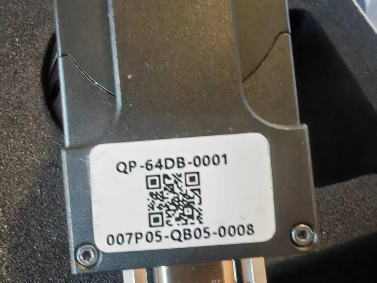
Whichever you choose, the drawing you want from the supplier is the one for your exact variant: hole pattern, connector positions, mechanical envelope, and the swing envelope the gimbal needs to reach its stated limits. Family-level datasheets are for shortlisting. Integration needs the model-level drawing.
Also ask where the centre of gravity of the head sits relative to the mounting face. It’s a small number to ask for and it saves an afternoon of arithmetic.
Weight, and where it goes
Payload weight is the first number most teams check, and usually the first one that turns out to be optimistic, because the quoted figure is for the head alone. Add the bracket, the connector, the cable run and the strain relief.
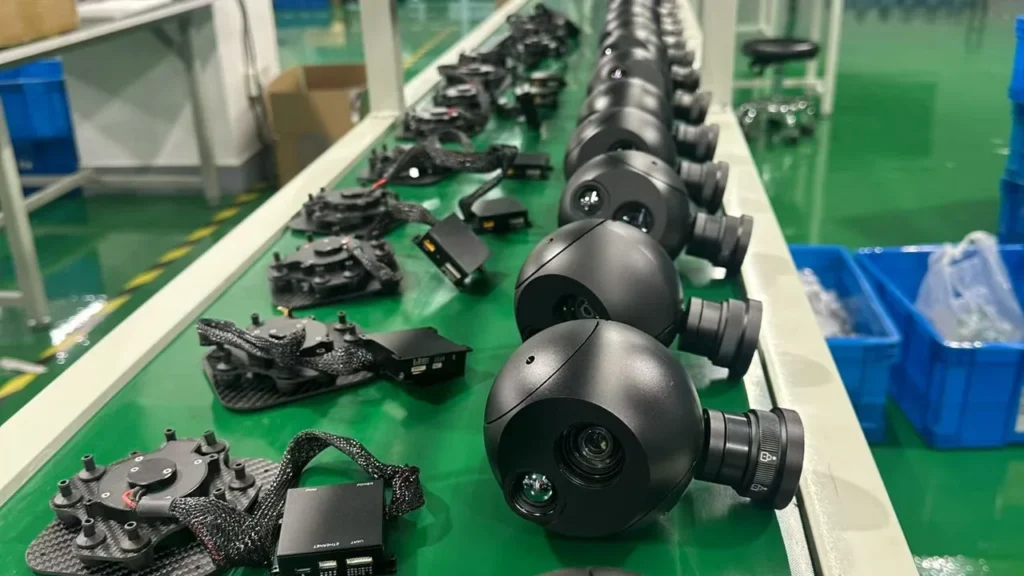
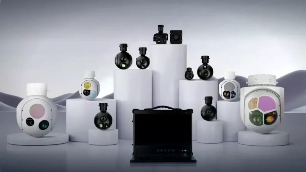
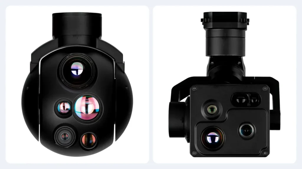
For orientation: the HITS HQ series spans a 240 g two-axis head up to a 1.5 kg three-axis turret. The XQ pod series starts around 1.6 kg and reaches 10 kg [7]. Two examples worth looking at as integration references:
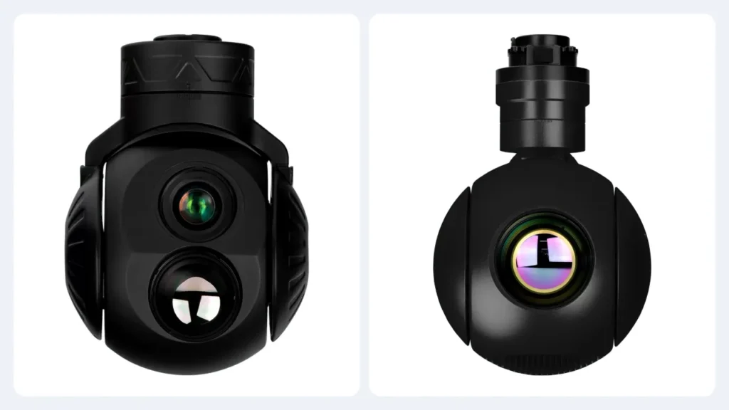
- HQ-64DA: a 260 g two-axis head with fixed daylight and a 640 × 512 thermal channel. The sort of payload you put on a small multirotor without redesigning anything.
- HQ-95Q: a 400 g three-axis head with a high-resolution daylight channel, thermal and an optional laser rangefinder. Same control architecture, noticeably more capability, still under half a kilogram.
Then check it against the airframe rather than the datasheet. A payload that’s inside the maximum take-off weight but sits behind the rear CG limit isn’t a payload you can fly.
Vibration, and why the gimbal on its own is not the answer
Motors, propellers and aerodynamic buffeting all push vibration into the airframe, and the payload sees whatever the mounting transmits. A good stabilisation loop rejects a lot of it. It doesn’t reject a resonance that the mount amplifies.
So evaluate the aircraft and the gimbal as a pair. If your platform has a known structural resonance, say so when you specify the payload. It’s a design input, not a complaint. And be careful with soft isolation: a mount that’s too compliant lets the head move relative to the airframe. That shows up as slow oscillation rather than high-frequency buzz, and it’s harder to tune out.
Clearance and cable routing
Check clearance across the entire movement envelope, not just at the neutral position. Then route the cable so that it doesn’t become a mechanical stop. Cables should have a service loop that flexes without pulling on the connector, be restrained either side of that loop, and be inspected after ground testing.
This is also where the payload connector’s position on the housing stops being a detail. A connector that faces the wrong way turns a tidy installation into a ninety degree adapter and a new bracketry problem.
Electrical integration
Electrical faults are the ones that damage hardware, so this part deserves a bench session before anything is bolted to an aircraft.
Voltage, current, and the startup transient
Confirm three numbers, not one: the input voltage range, the continuous current draw, and the peak draw during startup or axis acceleration. A head that settles at 15 W can spike to roughly twice that while the motors are spinning up. A power module sized on the steady-state figure will drop out at the worst moment.
The published figures for the HITS headquarters series are 11-28 VDC with a typical draw of 15 W and a peak of 30 W. Treat that as the starting point. Then check it against your own bus: what else is on that rail, what the regulator does when the load steps, and what happens on battery sag at the end of a flight.
Connectors, pinout and wiring
The single most expensive assumption in payload integration: that two connectors which mate are wired the same way. They aren’t, and the failure mode is a dead board. Work from the manufacturer’s approved wiring diagram for your model, and check the pinout with a meter before the payload is ever connected to a live bus.
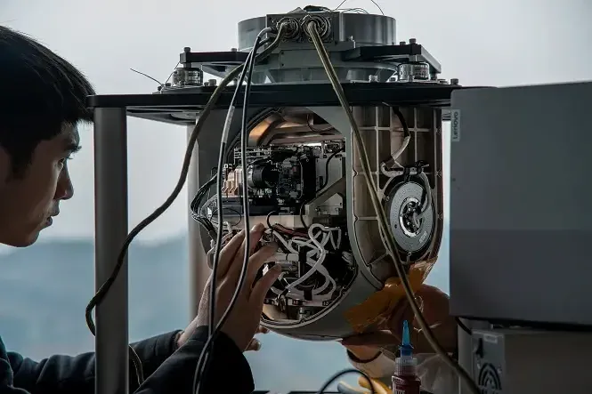
Four things to settle before you cut any cable: the mating connector on the payload side, the wire gauge the current actually needs, the service loop length that lets the gimbal move through its full range, and where the strain relief is anchored. Cable length is not free either. Long unbalanced runs are the usual reason a payload that worked on the bench starts dropping commands in the air.
Grounding and electromagnetic interference
UAVs put motors, switching regulators, radios and high-current wiring within a few centimetres of sensitive signal lines. That isn’t a design flaw, it’s the environment. What matters is that you plan for it.
- Keep video and control cabling away from motor phase and high-current battery wiring, and cross at right angles where they must cross.
- Ground the payload to the airframe’s single reference point, and be deliberate about whether that’s the same point your video ground uses.
- Screened cable is worth the weight on long runs, but only if the screen is terminated properly at both ends. A floating screen is decoration.
- Share the connector drawing with whoever wires the harness, and the EMI layout with whoever routes it.
If video quality degrades only when the motors are running, you have a grounding or coupling problem, not a camera problem. Worth knowing before you spend a week blaming the payload.
Protection and fault behaviour
Decide what the integration protects, and how. Overcurrent and reverse polarity protection on the payload rail are cheap insurance. So is knowing what the payload does when the input sags. Does it recover, or does it need a power cycle? Ask the supplier. The answer is a design input for your own power architecture.
Communication interfaces
This is the area with the widest gap between what a specification says and what it means.
The interface is not the protocol
A payload can have an RS-422 port and still not implement MAVLink on it. It can have an Ethernet port and still not stream RTSP. The physical layer tells you which wires to connect and nothing at all about what those wires will understand.
Ask two separate questions. First: what are the physical interfaces, and what’s on each one? Second: on the physical interface I want to use, which command protocol is implemented, at which version, and which commands within it? Suppliers who answer both questions well are the ones worth working with.
Physical interfaces you will meet
| Interface | Electrical layer | Typical job on a payload | Wiring reality | What to confirm |
|---|---|---|---|---|
| RS-232 | Single-ended, roughly ±5 to ±15 V | Control from an operator handset or an older ground station | Three signal wires plus ground, short runs | Voltage levels, baud rate, pinout, and what runs on top of it |
| RS-422 | Differential pair | Control from a flight controller or companion computer | Four wires plus ground, tolerant of longer runs and noisy buses | Whether the command set is MAVLink or proprietary |
| TTL UART | Logic level, 0 / 3.3 V | Direct link to a companion computer or a flight controller UART | Three wires; never connect direct to RS-232 levels | Logic level, baud rate, and whether it shares the command set of the RS-422 port |
| Ethernet | 100BASE-TX twisted pair | Video streaming, sometimes control on a separate service | Two pairs; connector and cable bulk cost space | Stream protocol, codec, IP addressing, ports, and whether control is separate from video |
| PWM / SBUS | Servo-style pulse, or serial SBUS | Simple position and mode commands from an RC link or flight controller | One signal wire per axis or one bus | Channel mapping, failsafe position, and which axis each channel drives |
| USB | USB 2.0 | Configuration, firmware update and bench setup | Short cable, bench use | Whether any USB function is intended for flight use at all |
| MAVLink | Protocol, not a physical layer | Gimbal orientation, camera commands, status reporting | Runs over serial or UDP; inherits the limits of that link | Protocol version, supported message set, and which component owns control |
What a usable interface control document contains
The ICD is the document that decides how long integration takes. A short, accurate one is worth more than a thick, vague one. At minimum it should pin down the following for your specific model.
| Integration item | What has to be confirmed |
|---|---|
| Physical interface | Connector type, mating half, pinout and electrical standard |
| Communication settings | Baud rate, IP addressing, port numbers and stream URLs |
| Control protocol | Protocol and version, and whether MAVLink is implemented at all |
| Gimbal commands | Pitch, yaw, rate, mode selection and who owns control |
| Camera commands | Zoom, focus, recording and imaging modes that are actually implemented |
| Video output | Stream protocol, codec, resolution, frame rate and bitrate options |
| Status and feedback | What the payload reports, in what message, and how often |
| Documentation control | ICD revision number and the firmware build it applies to |
If a supplier can’t produce a document like this, that’s itself useful information, and it’s better to discover it during evaluation than during delivery.
MAVLink and gimbal control
MAVLink is where most integration confusion lives, because “supports MAVLink” can mean anything from “the pilot can nudge the camera with a dial” to “a companion computer has full programmatic control”.
What MAVLink actually is
MAVLink is a lightweight message protocol. It defines message formats, not wires: commands and telemetry travel over whatever physical link you already have, which in practice means a serial port or UDP over Ethernet. That’s why the same camera can be described as both “RS-422 controlled” and “MAVLink controlled”, and why neither statement on its own tells you very much.
For gimbals there’s a dedicated Gimbal Protocol v2 covering orientation, status reporting and control management [1], and a separate Camera Protocol for imaging functions [2]. They’re two services. A payload can implement one, both, or neither.
Gimbal manager and gimbal device
Gimbal Protocol v2 splits control into two roles, and knowing which one your payload implements is the single most useful question you can ask about MAVLink compatibility.
If the payload is a gimbal device and your flight controller provides the manager, you’re in the configuration most autopilots expect. If both sides claim to be managers, or neither does, you’ll spend a week discovering that in flight testing.
Working with PX4 and ArduPilot
Both major autopilots document gimbal control, and both support more than one way of doing it. PX4 describes mount configuration using RC inputs or MAVLink commands, with the output set up according to the connected gimbal [3]. ArduPilot documents commands such as MAV_CMD_DO_GIMBAL_MANAGER_PITCHYAW together with the status messages it expects back [4].
That support is on the autopilot side. It doesn’t transfer to the payload automatically. An autopilot that implements the manager role is only half of a working link. The payload still has to implement the device role, at a compatible protocol revision, with the specific commands you intend to use.
Why the supported command list has to be verified per model
Two payloads can both advertise MAVLink support and still behave completely differently. Before you commit, get answers to these, for the exact model and firmware build you’re buying:
- Which MAVLink protocol version, and which revision of the gimbal service?
- Does the payload act as a gimbal device, a manager, or both?
- Which gimbal control messages are implemented: angle, rate, mode selection, retract and neutral?
- Which camera functions are exposed over MAVLink, and which need a separate proprietary channel?
- What status and acknowledgement messages come back, and how often?
- How is control ownership handled if two sources issue commands at once?
- Which firmware version introduced the current behaviour, and is it released or a development build?
A bench demonstration with your intended autopilot and ground station is the cheapest possible acceptance test. Do it before the aircraft is finished, not after.
Video and the ground station
Video is the one part of the payload chain the operator notices immediately, and the one most often tested under conditions that don’t resemble the mission.
What the stream actually is
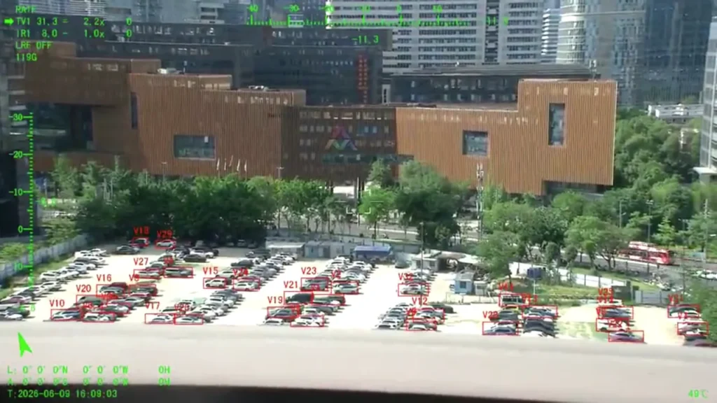
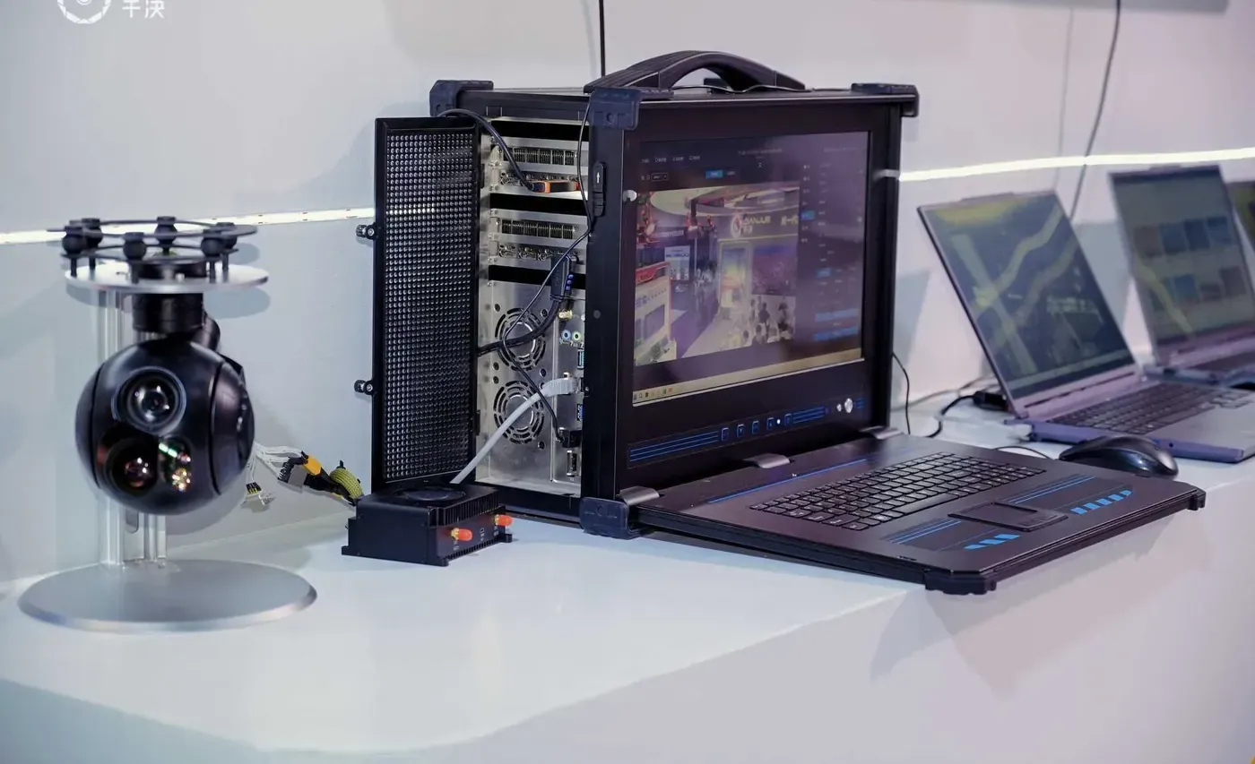
Ask for the stream definition, not the word “Ethernet”. You want the protocol (RTSP is the common one, but UDP H.264 and UDP H.265 are also widely used), the codec and profile, the resolution and frame rate options, the bitrate range, the IP addressing behaviour, and the port numbers.
Ground stations are particular about this. QGroundControl, for example, documents video source options including RTSP, UDP H.264 and UDP H.265 depending on how the software is configured [5]. The payload output has to match what your ground station can actually ingest, and that’s a two-sided conversation.
Resolution, frame rate and the bill you pay for both
Higher resolution means more detail in the frame and more data in the pipe. Every step up in resolution, frame rate or bitrate has to be paid for somewhere: in the encoder on the payload, in the data link, or in the ground station’s decode budget.
The practical approach is to define the minimum that satisfies the mission and test at that setting. A 1920 × 1080 stream at a realistic frame rate that never drops is worth more to an operator than a higher-resolution stream that stutters whenever the link degrades.
Latency, and why a lab cable proves nothing
Total latency is the sum of capture, encode, transmission, network queueing and decode. On the bench, over a one metre cable, it looks excellent. Over a real data link with a real bitrate, it’s whatever the slowest stage allows.
So test over the link you’ll actually fly with. If the payload offers a lower-latency mode or a lower bitrate profile, test that too, and decide which you prefer before the customer does.
Display, switching and recording
Three things get missed here. Can the ground station display the channels the way the operator needs, including switching between daylight and thermal without losing the other stream? Does the recording happen on the payload, the ground station, or both, and if the link drops, which recording survives? And do the timestamps, file formats and playback actually line up with whatever the customer uses to review the footage afterwards?
Recording on the payload is the more forgiving option, and it’s the reason airborne storage matters even when the aircraft has a working downlink.
SDKs, APIs and custom development
Most integrations never touch an SDK. The ones that do usually need it for a specific reason, and it’s worth being clear about which reason applies to you before you plan for development time.
When you actually need one
You need an SDK or an API when the standard toolchain can’t reach a function you’ve sold to a customer. Three examples: a custom user interface that combines camera control, telemetry and video in one window; an autonomy routine that has to point the camera at something without a human moving a joystick; a workflow where image capture is triggered by a flight event rather than a button.
You don’t need one to make the payload visible to the autopilot and the ground station. That’s protocol work, not software development, and if a supplier is suggesting an SDK for it, ask why.
What to ask for
- The documented command set, with a version number attached to it.
- Whether standardised libraries are supported. MAVSDK, for example, provides a gimbal plugin for devices implementing Gimbal Protocol v2 [6] – useful, but only where the payload implements the same service.
- Whether there’s a documented API of the supplier’s own, and whether it’s stable or still changing.
- Sample code that runs against a real unit, not a fragment in a PDF.
- A named engineer who will answer questions, and roughly how quickly.
One honest warning about SDKs: a rich SDK isn’t automatically a good sign. Sometimes it means the standard protocols weren’t implemented properly and everything has to go through a proprietary layer. Compare what the payload does over MAVLink with what it does through the SDK. The gap tells you a lot.
Integration testing: bench, ground, flight
Integration testing is cheap relative to integration failure. Running it in a fixed order also means that when something breaks, you already know which change caused it.
| Stage | What you’re checking | Evidence worth keeping |
|---|---|---|
| 1. Documentation review | Drawings, pinout, protocols, firmware version and the supported command list | A signed-off integration checklist and the document revisions it refers to |
| 2. Bench test | Power, startup behaviour, command response, video output and link stability | A test log with the firmware build, plus recorded video from both ends |
| 3. Ground test | Mounting security, full movement envelope, cable clearance, balance and interference | Photographs of the installation and a mechanical inspection record |
| 4. Flight test | Stabilisation under real vibration, video continuity, command behaviour under manoeuvre | Flight footage, telemetry logs and a written result against each acceptance criterion |
| 5. Acceptance | Every required function demonstrated, with defects listed and closed | A signed acceptance record, and a list of deferred items if there are any |
Stage 2: the bench test
The bench is where you want to find problems, so make it unkind: the real power supply, the real harness lengths, the real autopilot, the real ground station. Confirm supply voltage at the payload connector under load, not at the regulator output. Confirm startup behaviour, including what happens if the input dips. Then exercise every command you intend to use and record which ones respond.
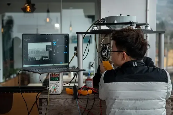
Video belongs in this stage too. Check that the stream appears, that the codec and resolution are what you expected, that the ground station can record it. Then check the one people forget: that it reconnects by itself after the link is interrupted.
Stage 3: the ground test
Once the payload is on the aircraft, the questions change from “does it work” to “does it still work here”. Move the head through its complete range and watch for anything touching: the airframe, the landing gear, the cable. Check the balance and the CG position again, with the aircraft fully loaded and the gear in the flight configuration. Run the motors at flight RPM on the ground if your procedure allows it, and watch the video for noise that only appears with the motors running.
Stage 4: the flight test
Flight testing is where stabilisation, video continuity and command behaviour meet real vibration and real manoeuvring. Fly the profiles the mission actually uses, including the unglamorous ones: a long transit at cruise, a hard turn, a descent. Then review the footage and the logs against the criteria you wrote down in stage 1.
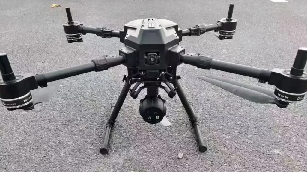
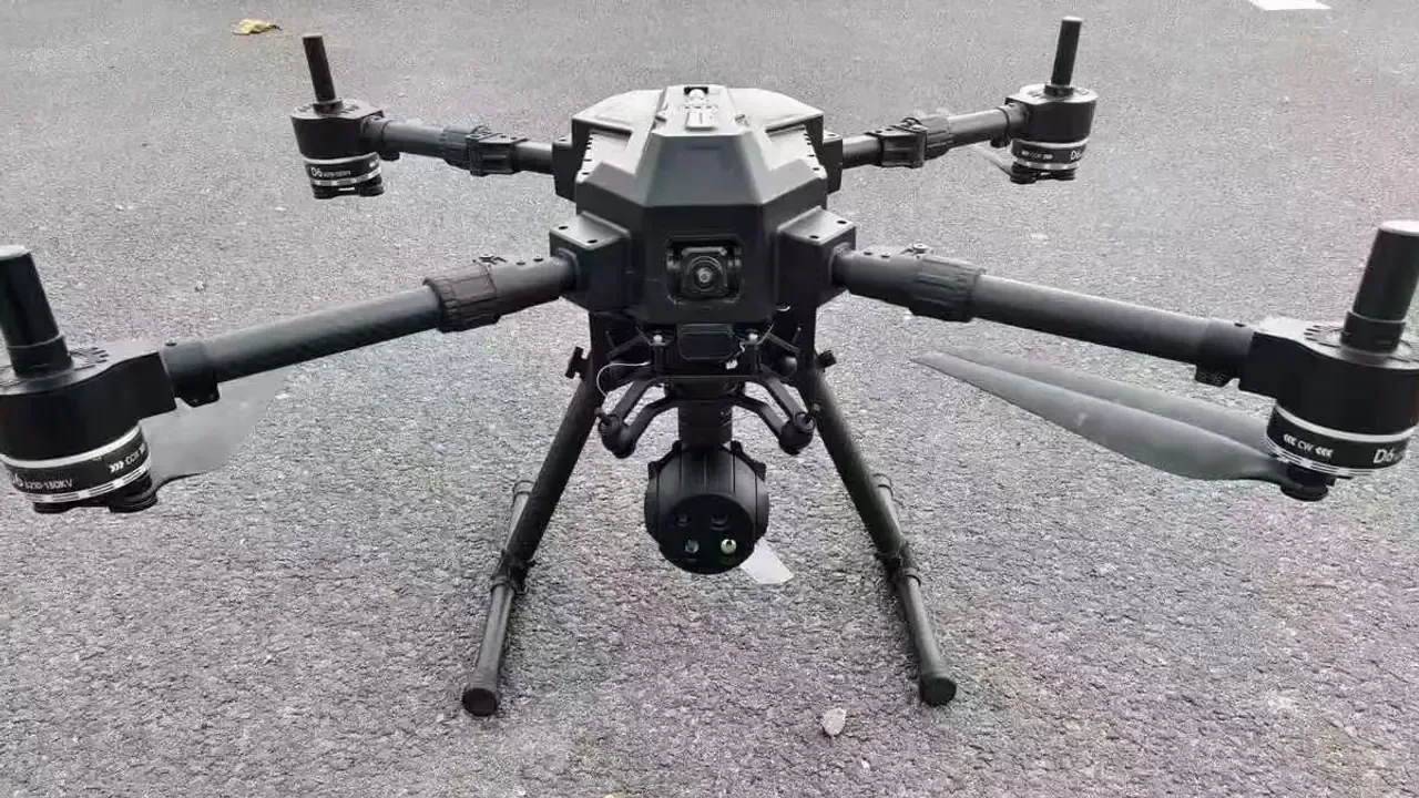
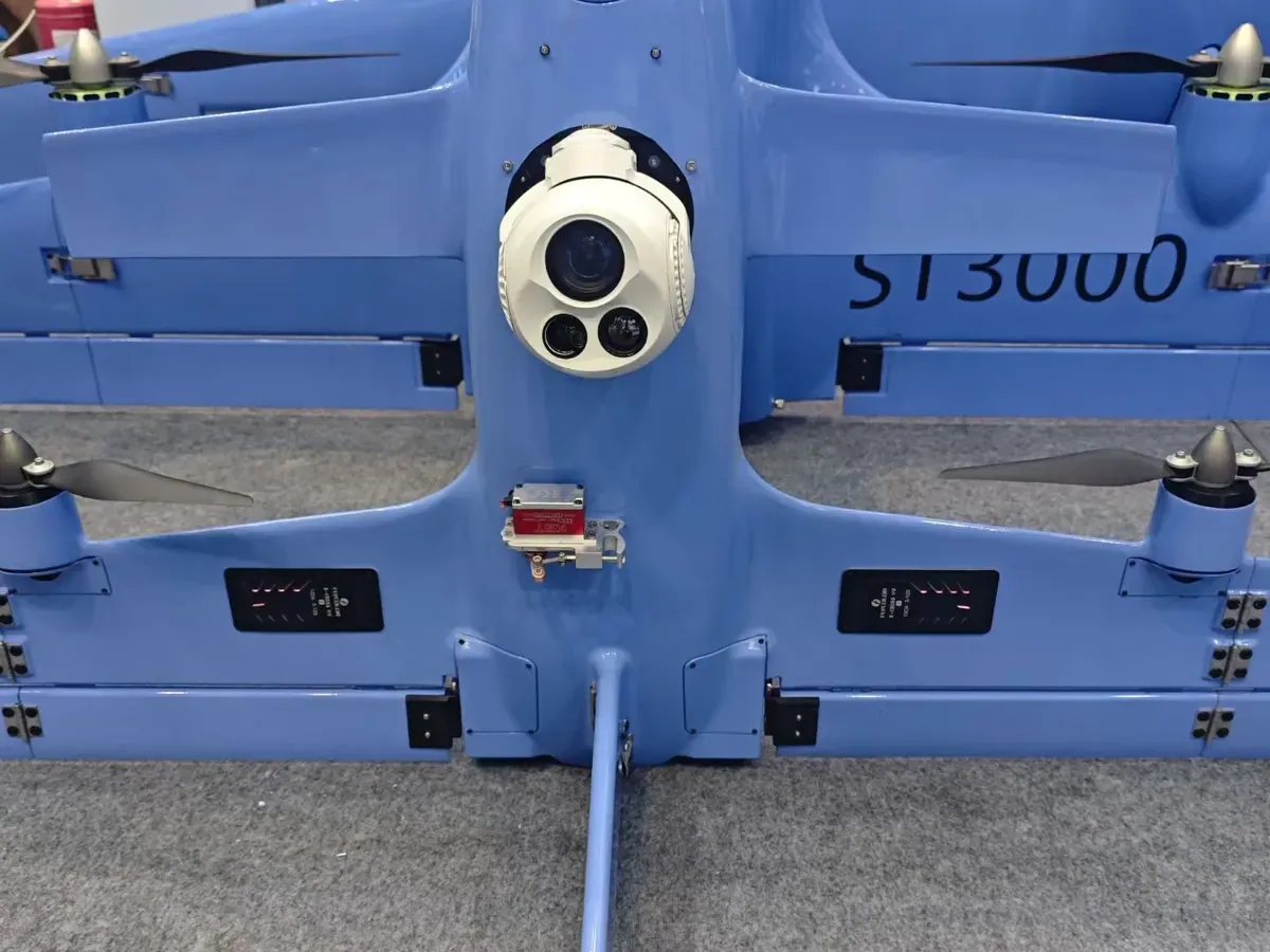
Gimbal and imaging payload testing on an industrial VTOL project. Source: HITS.
Acceptance criteria, decided in advance
“It works” isn’t an acceptance criterion. Something like “the operator can hold a person-sized target in the centre third of the frame while the aircraft orbits at the mission radius, and the recording is continuous for the full sortie” is. Write the thresholds before testing, agree them with the supplier, and measure them the same way twice.
Keep a defect list with an owner and a status. Most integration arguments aren’t about engineering, they’re about whether something was ever agreed to be in scope, and a list settles that in one meeting rather than three.
Working with a gimbal camera manufacturer
Most of the technical risk in a payload project is created or avoided before anyone signs a purchase order. It comes down to what you asked the supplier for, and whether they answered in documents or in adjectives.
What to send before integration starts
Suppliers can’t recommend a payload from an aircraft name alone. Send the following, even if some of it’s still provisional – a rough number you can revise is more useful than a blank field.
- Aircraft type and configuration: multirotor, fixed wing, VTOL, helicopter or tethered platform, plus the approximate maximum take-off weight.
- Available payload capacity: the mass you can actually spend, including the bracket, the cable and the connector, not just the head.
- Mounting intent: belly, nose, or a turret position, with the connector access you have.
- Power: the rail you intend to use, its voltage range, its current budget and what else sits on it.
- Flight controller and firmware: make, model and the version you’ll fly, not the version in the manual.
- Ground station: the software, and how you expect video and control to reach it.
- Imaging objective: what the operator has to see, at what distance, in what conditions, and whether you need recording in the air.
That list turns a vague enquiry into a specification conversation, and it usually shortens the back-and-forth by weeks.
Ask for documents by name
“Send me the technical documentation” gets you a brochure. Ask for the specific items instead: the outline drawing for your variant, the connector pinout and mating part, the electrical specification including startup transient, the interface control document, the supported command list with a firmware version attached, and the video stream definition. If a supplier can’t produce these, that’s itself the answer.
One more thing worth requesting early: the revision history. Ask which document revision applies to the unit you’ll be shipped, so that what you integrate against is what arrives.
Samples, and what customisation actually costs
An evaluation unit on your own airframe tells you more in a week than a month of email. Ask whether stock samples exist for the configuration you want, what the delivery time is, and whether the sample is the same build as production.
If you need changes, be specific about which layer they sit in: a bracket is mechanical work, a connector swap touches the harness, a protocol change touches firmware and the release schedule. Suppliers who tell you which of those they own, and which they don’t, are easier to plan around.
Support that outlives the delivery
The questions that matter after handover are boring and practical. Who answers a technical question, and in which time zone? What’s the route for a repair, and how long does an aircraft stay grounded? Can individual modules be replaced rather than the whole head? How will you be told about a firmware change that affects behaviour you already qualified?
Our own product range, inspection process and export documentation are all published. See the gimbal camera range, the quality control page and the export compliance page. Selected models in our range are controlled over MAVLink and are compatible with PX4 and ArduPilot, and the interface documentation for each model lists the commands it implements. Compatibility is confirmed per model and per firmware build, so ask our engineering team to confirm it for the exact unit you’re buying.
The review sheet worth filling in
Before you commit, write down what has to be true and who has checked it. The table below records what HITS confirms for selected models in the range, and it doubles as your own integration checklist, so add a row for anything your aircraft changes.
| Check | Confirmed scope | Evidence in the document pack | Status | Signed off by |
|---|---|---|---|---|
| MAVLink support | Supported on selected models, per the firmware build you’re buying rather than from the family datasheet | Supported message list with the protocol version and firmware revision it applies to | Confirmed | HITS engineering |
| PX4 compatibility | Confirmed on selected models, against the PX4 version you’ll fly, in the manager or device role you intend | Bench test result with your autopilot hardware and firmware | Confirmed | HITS engineering |
| ArduPilot compatibility | Confirmed on selected models, against your ArduPilot version, including the commands you plan to use | Bench test result, plus the parameters and setup notes used | Confirmed | HITS engineering |
| Supported protocol and message list | Confirmed on selected models: every function you’ve promised a customer is reachable over an interface you can actually wire | Interface control document and command list, revision controlled | Confirmed | HITS engineering |
| Interface and power support | Confirmed on selected models: voltage, current, startup transient, connector type and pinout all match your harness plan | Electrical specification, connector drawing and mating-part reference | Confirmed | HITS engineering |
| Document pack revision | Not tied to a model: the revision you integrated against is the revision shipped with the unit | Document list with revision numbers and dates | Confirmed | HITS engineering |
What’s left for your team is the aircraft side: your power rail, your harness lengths, your autopilot version and your mounting bracket. Those are the variables that decide whether a payload that works on the bench works in the air.
Compatibility statements on this page cover selected models. Before you order, ask us to confirm the exact model and firmware build you’re buying against your autopilot and ground station.
Frequently asked questions
Can every UAV gimbal camera support MAVLink?
No. MAVLink support depends on the hardware, the firmware and the protocol the manufacturer implemented. Even where MAVLink is present, the supported commands, the protocol revision and the status messages vary from model to model, and sometimes between firmware builds of the same model. Treat it as a per-unit question and ask for it in writing.
Which interfaces are commonly used for gimbal control?
Serial links are the most common: RS-232, RS-422 and TTL-level UART, usually for control from a flight controller or companion computer, and often a separate one for an operator handset. Ethernet appears on payloads that also stream video, and some models add model-specific connections. The electrical interface and the command protocol are two different questions, and both need an answer.
Can a gimbal camera work with PX4 or ArduPilot?
Often yes, but the compatibility isn’t automatic. PX4 and ArduPilot both document gimbal control, and both describe more than one way to do it. The autopilot side being ready only gets you halfway: the payload still has to implement the matching role at a compatible revision, with the commands you intend to use. Test it on your own hardware and firmware before you plan a programme around it. Selected models in our own range are controlled over MAVLink and are compatible with both, and the interface documentation for each model lists the commands it implements.
What technical documents should I request?
At minimum: the datasheet for the exact model, the outline drawing with the hole pattern and connector positions, the connector pinout and mating part, the electrical specification including startup behaviour, the interface control document, the supported command list with its firmware revision, the video stream definition, and any unit test or calibration record. If the supplier can’t provide these before the order, that’s worth knowing before the order.
Conclusion: reduce integration risk before you order
Integration is mostly a documentation exercise that turns into an engineering exercise when the documentation is missing. The mechanics, the power, the protocol and the video path each have to be agreed with a specific unit in mind. Each of them is cheaper to settle at a desk than on a runway.
One habit is worth keeping from this guide. When someone tells you a payload is compatible with your aircraft, ask which of the four things they mean: MAVLink compatibility, PX4 compatibility, ArduPilot compatibility, or support through an SDK. They’re four different claims with four different test procedures, and a supplier who can separate them for you is a supplier who has actually done the work.
Technical note: product capabilities, firmware support, electrical specifications and integration functions must be confirmed against current model-specific documentation before implementation. Published descriptions are a starting point, not a substitute for testing on your own aircraft.
Technical references and sources
The following sources support the protocol, flight-controller, video and software statements in this article.
- [1] MAVLink – Gimbal Protocol v2. Official definition of gimbal managers, devices, control and status reporting.
- [2] MAVLink – Camera Protocol v2. Official documentation for camera commands and functions.
- [3] PX4 – Gimbal configuration. Mount configuration, MAVLink gimbal control and supported input and output methods.
- [4] ArduPilot – Control a gimbal or camera mount. MAVLink gimbal commands and the status messages the autopilot expects.
- [5] QGroundControl – Video settings. Supported video sources and recording settings.
- [6] MAVSDK – Gimbal plugin. Developer documentation for MAVLink Gimbal Protocol v2 control.
- [7] HITS – Gimbal cameras. Product range and listed interface capabilities.
- [8] HITS – Quality control. Inspection and testing information.
Planning a payload integration?
Send us the airframe, the flight controller and firmware version, the interface you want to use, and your timeline. We’ll tell you what fits, what has to be confirmed, and what the documentation covers.
Related reading: our gimbal camera range, the thermal camera payloads and EO/IR camera payloads, how the units are built on the factory page, the inspection criteria on the quality control page, and the technology overview. If you’re still shortlisting suppliers, start with how to choose a UAV gimbal camera manufacturer in China.