
UAV Zoom Camera Technology: Optics and Stabilisation
Four engineering disciplines behind every HITS payload
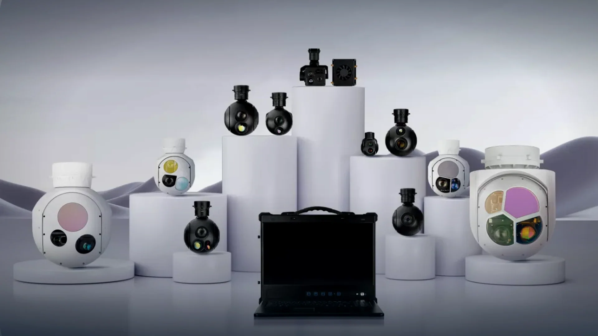
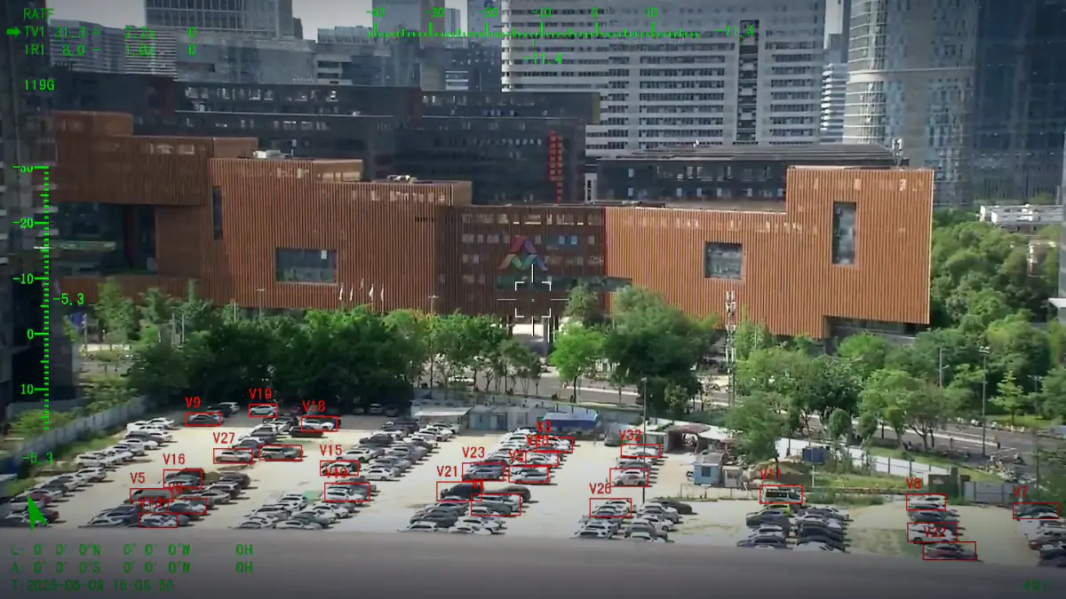
Every payload in the HITS range is built on the same four blocks: a continuous-zoom optical assembly, a gyro-stabilised mount, a boresighted imaging head and an onboard compute module that carries detection and tracking.
- Continuous zoom
- Three-axis stabilisation
- EO / IR imaging
- Onboard AI tracking
Technology pages
Three disciplines, each with its own constraints and its own vocabulary.
- Night imagingNight Vision
Thermal detectors, low-light visible channels and infrared illumination for operations after dark.
- RangeLong Range Imaging
Focal length, pixel density and jitter budgets that decide how far a payload can identify a target.
- TrackingAI Tracking
Onboard detection, lock and follow, multi-target tracking and target handover without ground-station compute.
A drone zoom camera is not a camera with a large lens bolted to a gimbal. Zoom ratio, entrance pupil and sensor format decide the field of view at both ends of the range, and the mount has to hold that narrower field steady, because every degree of airframe motion is multiplied by the focal length. A 30x zoom on a 129 mm lens leaves the line of sight about forty times more sensitive to vibration than the same head at 4.3 mm.
The pages below cover the three disciplines that decide whether a uav camera with zoom is usable in the field: night-time imaging, long-range imaging and AI tracking. If you are comparing a uav zoom camera against a cheaper gimbal zoom camera, the numbers to compare are angular velocity, stabilisation accuracy, focal range, detector pitch and interface, not the marketing zoom figure.
The four blocks every payload shares
- Optical zoom assembly
Continuous zoom from 4.25 mm to 300 mm depending on model, with autofocus, electronic image stabilisation and a lens coating set chosen for the 0.4 – 0.9 micrometre visible band.
- Gyro-stabilised mount
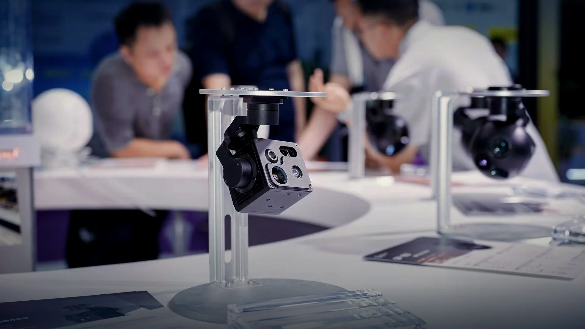
Two- or three-axis direct-drive brushless axes with high-resolution encoding, stabilisation accuracy to 100 microradians and angular velocity above 60 degrees per second.
- Boresighted imaging head
Visible, thermal and laser channels are aligned on one line of sight at the factory, so switching channel does not move the aim point on the operator display.
- Onboard compute and tracking
Person, vehicle, vessel and aircraft detection runs on the payload itself, which keeps tracking alive when the data link degrades or drops out entirely.
- Laser rangefinding
1535 nm or 905 nm rangefinders from 5 m to 15 km depending on class, turning a pixel on a screen into a georeferenced coordinate for the ground station.
- Control and video pipeline
Ethernet video with RS-422, RS-232, TTL, SBUS and MAVLink control, plus onboard recording so the mission record survives a lost link.
What changes as you move up the range
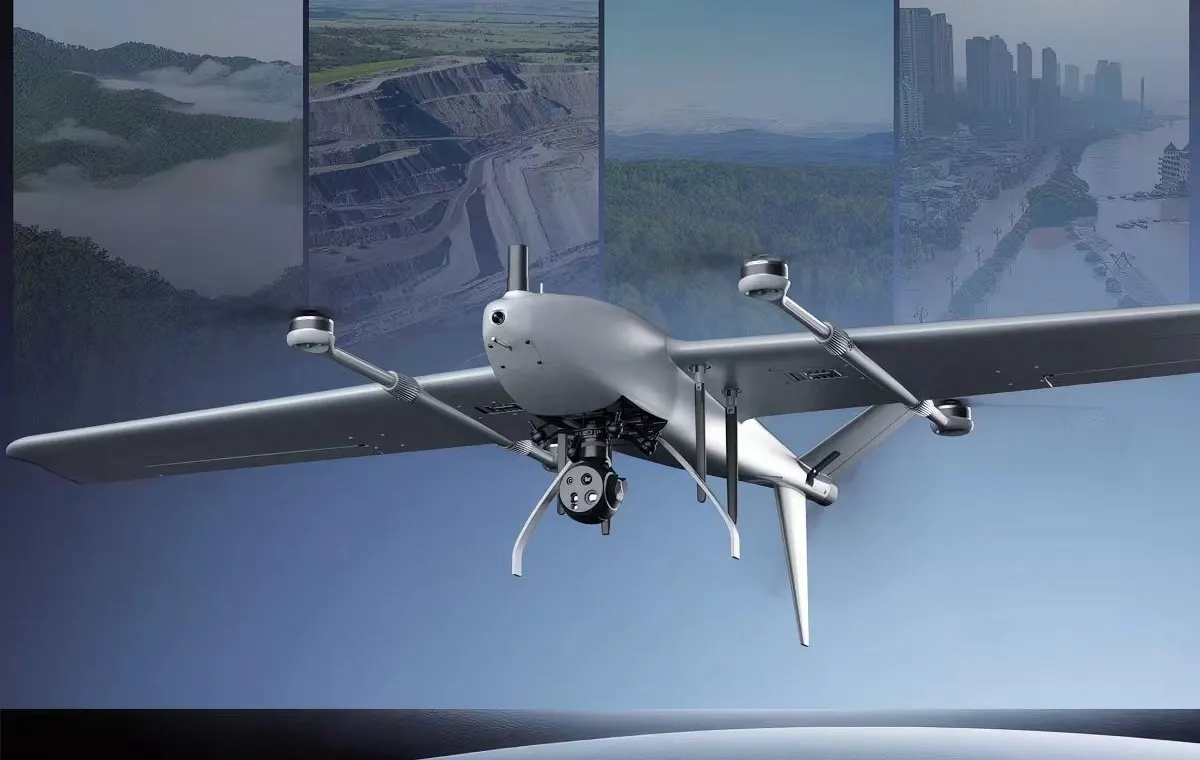
The same architecture scales from a 240 g multirotor head to a 22 kg targeting pod. These are the bands it moves through.
| Capability | Light class | Mid class | Heavy class | Pod class |
|---|---|---|---|---|
| Typical weight | 240 – 500 g | 800 g – 1.2 kg | 1.4 – 1.5 kg | 1.6 – 22 kg |
| Visible channel | 2688 x 1520 fixed, or dual 8 mm + 25 mm | 1920 x 1080 with 10x – 30x zoom | 1920 x 1080 with 30x – 40x zoom | Up to 3840 x 2160 with 17.5x – 55x zoom |
| Thermal channel | 640 x 512, 19 mm | 640 x 512, 25 – 35 mm | 640 x 512, 35 – 50 mm | 1280 x 1024, 75 mm, or 640 x 512 continuous zoom |
| Laser rangefinding | None or 1.5 km | 1.5 – 3 km | 3 km | 5 – 15 km, plus 1064 nm designation on SQ models |
| Mount | 2-axis or 3-axis | 3-axis | 3-axis | 2-axis pod turret |
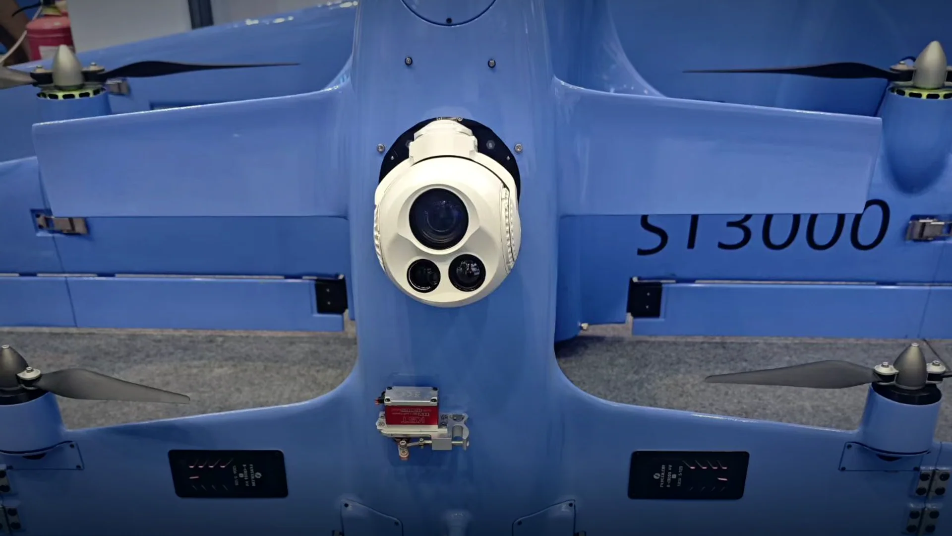
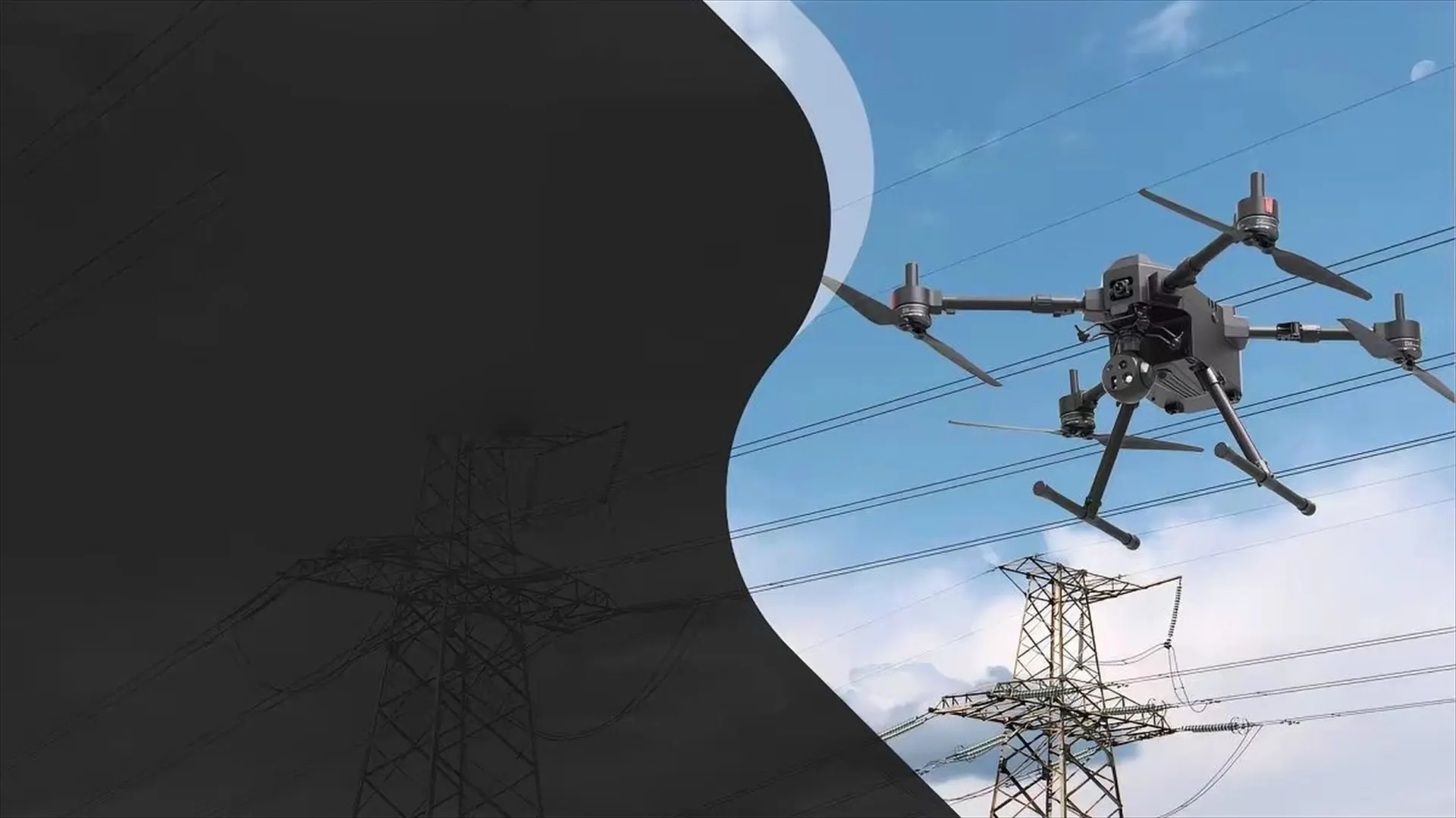
| Platform | Multirotor, small VTOL | Multirotor, VTOL, fixed wing | Fixed wing, helicopter | Helicopter, large fixed wing, UGV, USV |
Optical zoom and infrared, side by side
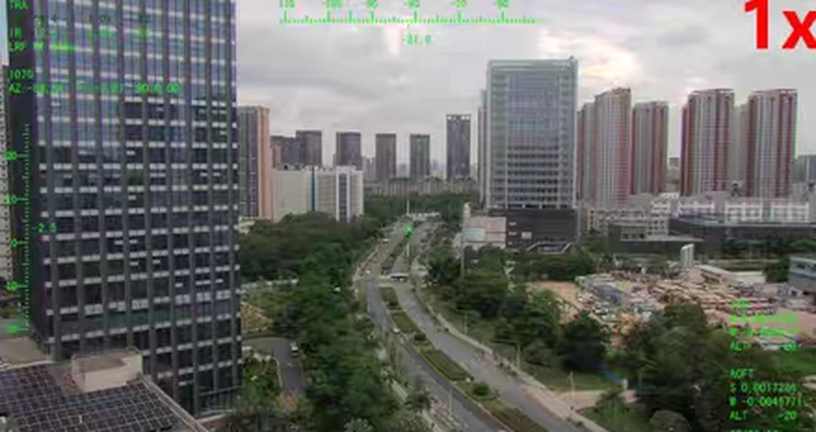
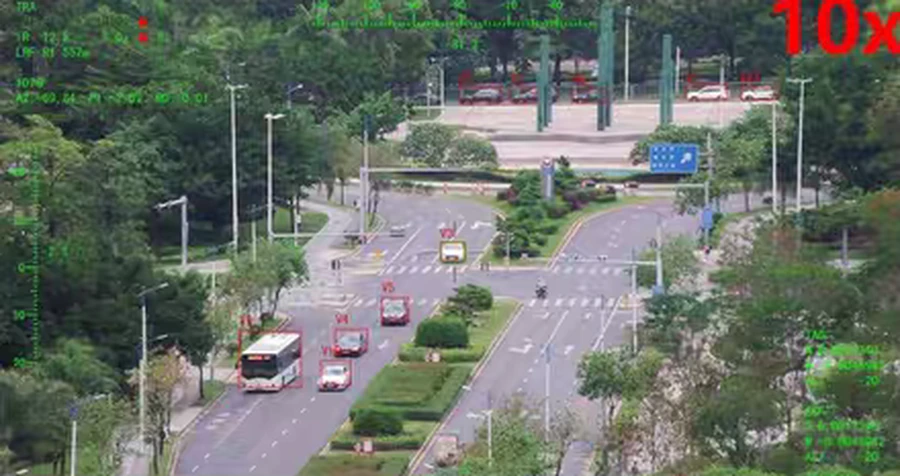
Four frames from the same payload: the wide daylight view, the same scene at 10× and 40× zoom, and the 640 × 512 infrared channel. The magnification is optical, so the detail is resolved by the lens instead of being interpolated from a smaller image.
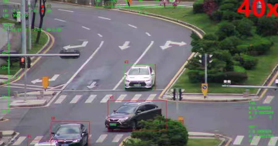
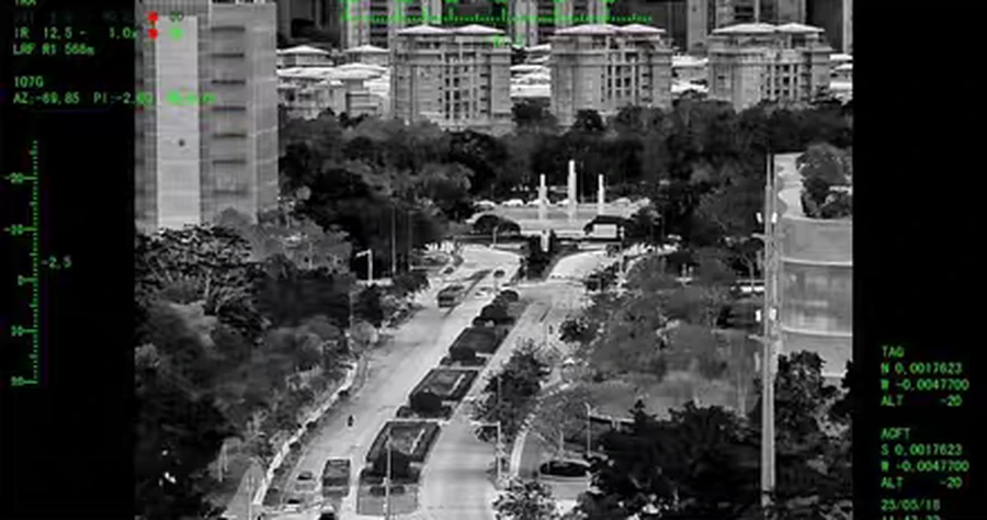
Zoom ratios, sensor formats and thermal resolutions differ between models — the product table lists them head by head.
Where this technology ships
Three examples across the range, from a 1.4 kg three-axis head to a 10 kg pod with a 15 km rangefinder.
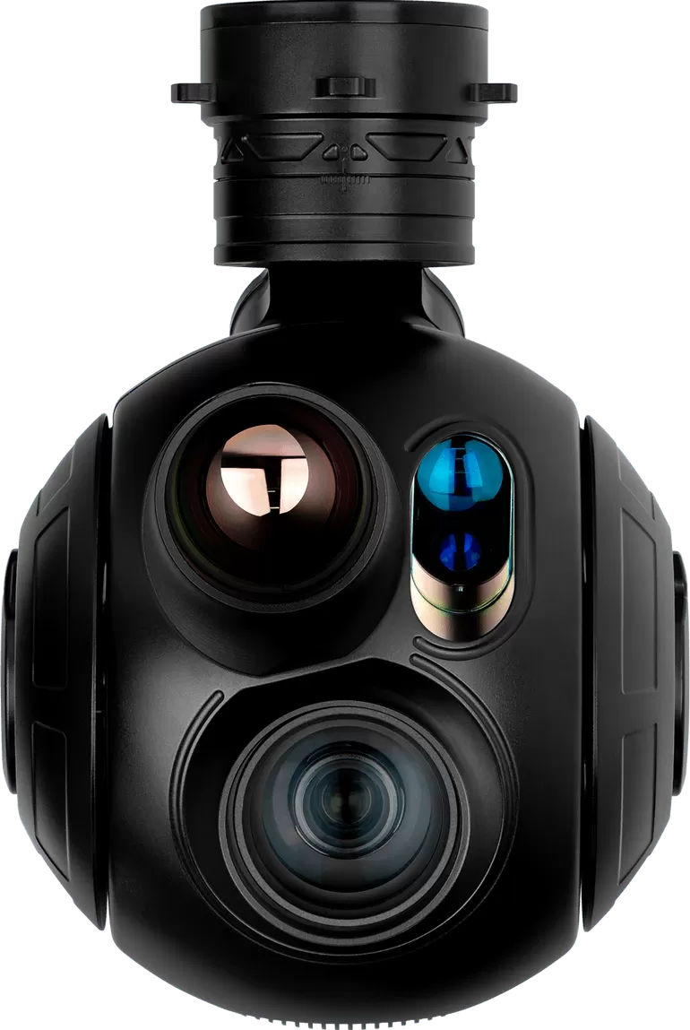
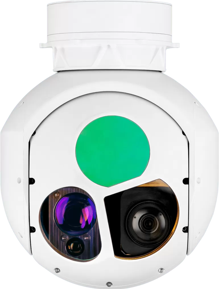
HQ · 3-axis · EO + IR + LRF
HQ-135T
The flagship of the compact range: 40x zoom, thermal imaging and 3 km ranging on one stabilised cage.
- Visible
- 1920 × 1080, 40x zoom 4.25 – 170 mm
- Thermal
- 640 × 512, 35 mm fixed
- Laser
- 15 m – 3 km (± 1 m)
- Weight
- ≤1.4 kg
XQ · 2-axis · EO + IR + LRF
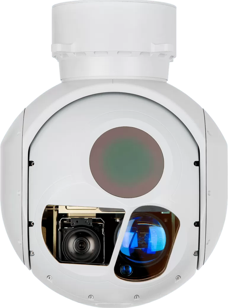
XQ-200T
A continuous-zoom thermal channel from 40 mm to 220 mm plus 9.5 km ranging on a 5 kg pod.
- Visible
- 1920 × 1080, 30x zoom 4.3 – 129 mm
- Thermal
- 640 × 512, continuous zoom 40 – 220 mm
- Laser
- 50 m – 9.5 km (± 1 m)
- Weight
- ≤5 kg
XQ · 2-axis · EO + IR + LRF
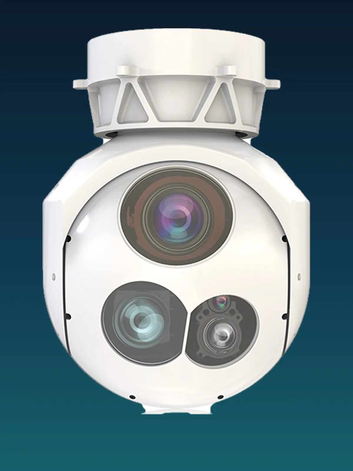
XQ-254T
The long-range pod: 15 km ranging and a 254 mm turret for maritime and border patrol aircraft.
- Visible
- 1920 × 1080, 30x zoom 4.3 – 129 mm
- Thermal
- 640 × 512, continuous zoom 40 – 220 mm
- Laser
- 100 m – 15 km (± 1 m)
- Weight
- ≤10 kg
Compare the range
| Model | Series | Axes | Configuration | Visible camera | Thermal imager | Laser rangefinder | Weight |
|---|---|---|---|---|---|---|---|
| HQ-135T | HQ series | 3-axis | EO + IR + LRF | 1920 × 1080, 40x zoom 4.25 – 170 mm | 640 × 512, 35 mm fixed | 15 m – 3 km (± 1 m) | ≤1.4 kg |
| XQ-200T | XQ series | 2-axis | EO + IR + LRF | 1920 × 1080, 30x zoom 4.3 – 129 mm | 640 × 512, continuous zoom 40 – 220 mm | 50 m – 9.5 km (± 1 m) | ≤5 kg |
| XQ-254T | XQ series | 2-axis | EO + IR + LRF | 1920 × 1080, 30x zoom 4.3 – 129 mm | 640 × 512, continuous zoom 40 – 220 mm | 100 m – 15 km (± 1 m) | ≤10 kg |
Related pages
The technology pages explain how the payloads work; the product pages list what is available.
- Gimbal camera seriesFifteen two- and three-axis heads from 240 g to 1.5 kg.Read more →
- EO/IR pod systemsEight larger pods with 30x – 55x zoom and ranging to 15 km.Read more →
- Night visionThermal, low-light and illumination for night operations.Read more →
- Long range imagingWhat decides how far a payload can identify a target.Read more →
- AI trackingOnboard detection and multi-target tracking.Read more →
Engineering decisions that show up in the video
Why continuous zoom beats stepped zoom
A stepped or dual-FOV lens forces the operator to choose between wide coverage and detail, and the moment of switching is usually the moment the target is lost. A continuous zoom lets the operator widen the field to find the object and then close in on it without an optical break, which is also what makes autofocus and tracking behave predictably.
Why the mount is harder than the camera
A camera is a component; a stabilised mount is a control system. Encoder resolution, loop rate, friction and cable stiffness all feed into the same error budget as the optics, and a good lens on a mediocre mount produces worse imagery than the reverse. That is why stabilisation accuracy and angular velocity are published next to the sensor data.
Why the compute moved onto the payload
Ground-station tracking depends on a link that can be jammed, crowded or simply out of range. Running detection and tracking on the payload means the lock survives a dropped link, and the operator sees the target framed the same way when the link returns.
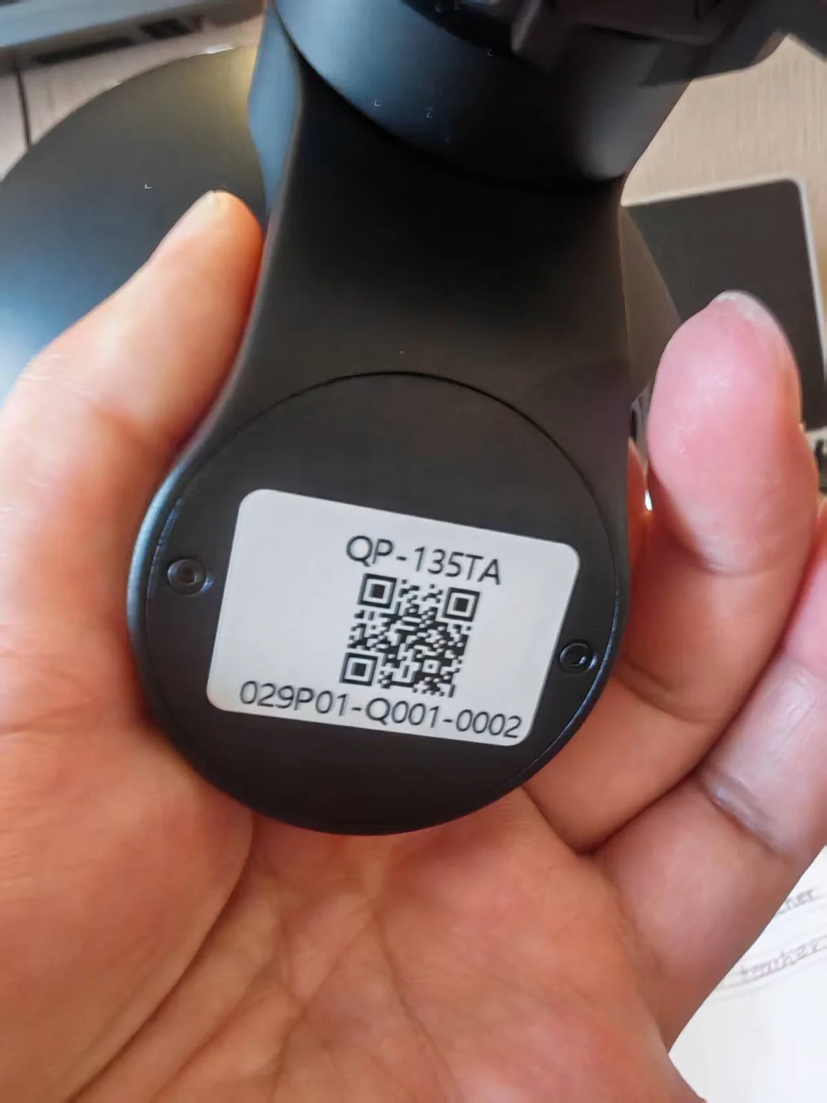
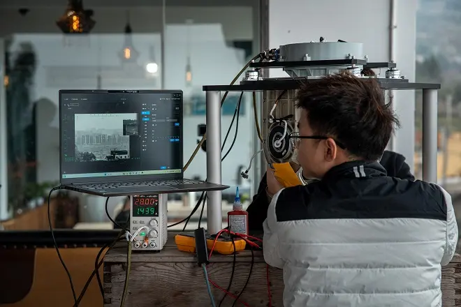
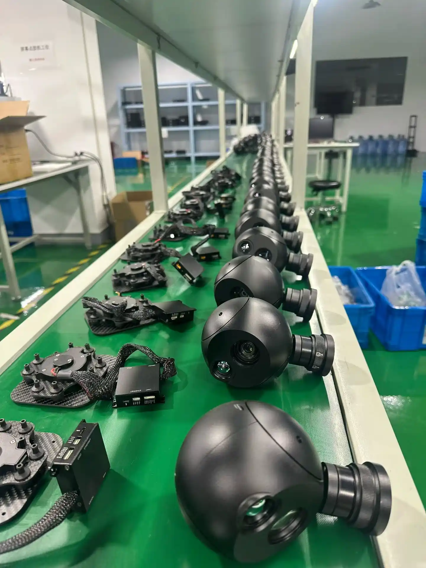
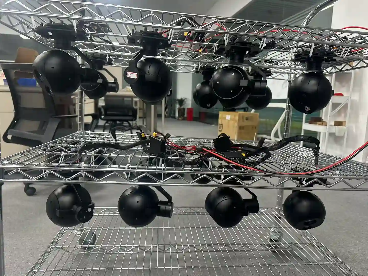
Designed and manufactured by HITS
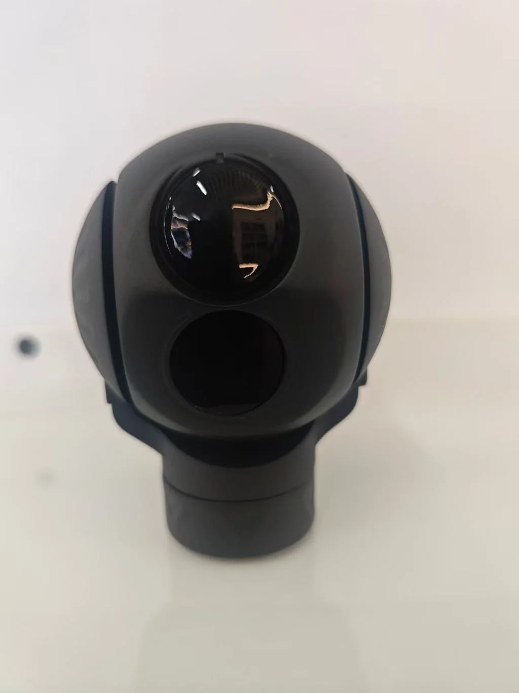
Optics, servo hardware, stabilisation firmware and the AI tracking module are developed in house, and every unit is assembled, calibrated and environmentally tested on our own line before it ships.
Related reading
Request information or a quotation
Tell us the mission profile and we will point you at the technology and the model that fits it. Contact us with your requirements.